Difference between revisions of "TBS Discovery setup"
| Line 1: | Line 1: | ||
A guide and a few notes on how I set up my TBS Discovery. Obviously, your setup will most likely differ from the following example, but this is is still useful as a basis to continue tweaking your own setup. | [[Image:TBS Discovery box contents.jpg|400px|right]]A guide and a few notes on how I set up my TBS Discovery. Obviously, your setup will most likely differ from the following example, but this is is still useful as a basis to continue tweaking your own setup. | ||
* [[TBS Discovery|Back to TBS Discovery]] | * [[TBS Discovery|Back to TBS Discovery]] | ||
Revision as of 15:05, 5 February 2013

A guide and a few notes on how I set up my TBS Discovery. Obviously, your setup will most likely differ from the following example, but this is is still useful as a basis to continue tweaking your own setup.
Flight controller
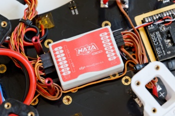
- DJI NAZA-M flight controller
- DJI PMU BEC power module
- Micro-USB cable
- 4x 3M Gummed anti-vibration pads
- 8x 3-pin Servo cables

The follwing setup and configuration will show how to install the DJI NAZA kit on a quadrotor platform. Mount the controller in the center of the frame and preferably close to the Center of Gravity (not strictly important). The arrow on top of the unit should match the forward direction.
Motor configuration
Two of the four motors rotate in the opposite direction to provide the necessary counter-torque force.
The image to the right shows how the speed controllers should be plugged into the DJI NAZA controller. Be sure to double check this before the first maiden flight, else the quad will violently turn over.
Motor configuration:

- M1: Anti-clockwise rotation
- M2: Clockwise rotation
- M3: Anti-clockwise rotation
- M4: Clockwise rotation
Gains
Attitude here refers to the auto leveling feature of the NAZA controller when the input sticks are zeroed/centered, while manual refers to the rate mode where you have to continuously adjust the control input to change the flight angle.
Setup 2012-08-19
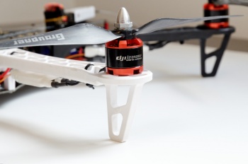
- DJI 2212 920KV 144W brushless motors
- Graupner E-Prop 10x5 inch propeller set

The NAZA flight controller gains in the Autopilot section will dominate how well and stable the quadcopter will behave in the air.
Manual rate:
- Roll 145%
- Pitch 150%
- Yaw 125%
- Vertical 150%
Attitude:
- Roll 125%
- Pitch 125%
Follow the steps below to tune and get a smooth but responsive vehicle.
- Reset any aileron, elevator or rudder expo and dual rates programming, same for throttle curve
- In NAZA Assistant set the default values of 130% for all the basic rate gains and 100% for attitude gains
- Start by focusing on roll (aileron) and pitch (elevator), start by increasing one value at a time by 20% and perform a test flight
- Pluck the aileron stick back and forth to give full input and release it to center immediately to simulate a sudden squarish change of input, the important part here is to watch for overshoot or wobbly overcorrection, if not seen increase by another 20%
- Once the twitchy overshoot reaction appears it means that the correction is too reactive, start to lower in 10% steps until the correction behavior is smooth again and settles fast, but still responsive, look at the figure to the right for an idea - my roll ended at 145%
- Do the same for roll by pulling full forward and backward stick and watch for wavy corrections on the tail end of the quadcopter - my pitch ended at 150%
- Yaw (rudder) gain is easier, increase by 10% and turn fast, if the flight controller overcorrects in a violent fashion, decrease by 5% - my yaw ended at 125%
- The last in basic gains, vertical controls the height when the throttle stick is in altitude holde position a.k.a. middle center stick - my vertical ended at 150%
- Lastly, the attitude gains reigns the transition between stable to desired angle (degrees/s), increasing them will move the quadcopter into position faster - my attitude gains ended at 125% for both
A note about the airframe, since it is asymmetrical and the weight is distributed rectangularly from back to front along the center line, the pitch will always be higher than the roll gain (more mass to move results in delayed reaction thus requiring steeper correction ranp).
- WKM Detailed Descriptions on Autopilot parameter setting
- OpenPilot Stabilization Configuration
- OpenPilot Stabilization Tuning for Multirotor
- PID Without a PhD
Speed Controllers
- 4x DJI OPTO 30A ESC with on-board 3.5 mm bullet sockets
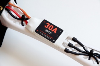

Using the stock DJI speed controllers is fairly straight forward, just connect the motor, power leads and control signal wire. But if you want to use another type make sure to that the following is true:
- Fast PWM control signal update frequency, 400 Hz - fast motor response (check SimonK, WiiESC, RapidESC)
- Calibrate the throttle range on each ESC - for symmetric behavior of all ESC
- Only one 5V BEC should be connected to power the flight controller - disconnect the others to avoid voltage oscillations
- Strap the wires not the ESC board - less strain on the heatsink and transistors
Battery
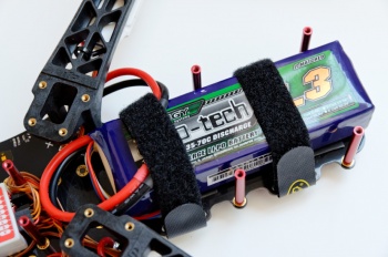
- Turnigy Nano-tech 4S 3300 mAh Lipo pack
- Zippy Compact 4S 4000 mAh Lipo pack
- 2x Scorpion Battery Lock Strap large
- Deans compatible T-connectors

The largest battery that fits battery cage is W55xH37xL173 mm, but a typical 4500 mAh pack is 44x31x147 mm which fits just barely. To get the Center of Gravity right, the battery weight should be within 320 to 460 grams, which corresponds to 3300 and 4500 mAh respectively. It's also worth mentioning that cheaper Lipo packs (Nano-tech, Zippy) will not necessarily deliver the claimed specs (C-rating). Improper handling will fairly quickly puff and reduce the life-time of the pack.
Use either TBS or Scorpion large battery straps to fasten the batter pack. To limit the amount of scratches on the bottom plate, put a few soft foam pads along the bottom cage.
Keep the main power cable (to the battery) on the bottom plate as short as possible to minimize any tangling, damage to the cable or unexpected disconnects. Insert the battery with the cable main power lead connected to the battery and with the cable protruding from the back, measure along the right side of the cage, and cut the main power lead to find the right amount of cable slack.
Transmitter
Setup 2012-08-19

- Spektrum DX7 with:
- FrSky DHT 2.4GHz 2-way 60mW transmitter
- Or ImmersionRC EzUHF 433 MHz 200mW/600mW transmitter
This transmitter has 7 channels is programmable for both airplanes and helicopters. It has a 3-way flap switch, aileron and elevator dual rate switches, rudder mix switch, gear and aux2 switch. A preset memory makes it possible to set up several different models on the same radio.
System settings (holding down+select when powering on):
- Model type:
- Heli
- Input select:
- Aux2: F.mode - to enable three stage flight mode
- Gear: Inh
Settings (other than defaults):
- Reversing sw:
- Channel 5 and 7 reverse for flight mode, others normal
- Sub trim:
- Gear -7 - for positioning the Attitude flight mode in DJI Assistant setup
- Travel Adjust - adjusted for maximum resolution
- THRO H 140% L 140%
- AILE L 140% R 140%
- ELEV D 140% U 140%
- RUDD L 140% R 140%
- GEAR + 84% - 84% - position the end-points to fit Attitude GPS and Manual flight modes
- PIT H 100% L 100%
- AUX2 + 100% - 100%
- Throttle curve - to make it easy to maintain height, flat in the middle
- ST-1 - Attitude mode
- Point 1: 35%
- Point 3: 65%
- Prog. Mix1 - to provide three position flight mode
- AUX2 -> Gear ON
- Rate: +100%
- SW: ON
- Offset: 0
- D/R & Expo
- POS-0: - attitude mode
- ELEV EXP +50% D/R 100%
- AILE EXP +50% D/R 100%
- RUDD EXP +20% D/R 100%
- POS-1:- manual rate mode
- ELEV EXP 60% D/R 80%
- AILE EXP 60% D/R 80%
- RUDD EXP 30% D/R 80%
- POS-0: - attitude mode
Enable flight mode switch
When using Spektrum DX7 only the Gear-channel is available on the receiver end. To be able to use the three-position switch, it is necessary to set the Aux2-channel to F.mode (Flight mode) and map the Aux2-channel to Gear [1].
- Enter system mode, hold down left hand buttons while powering on and scroll to Input Select
- Set Aux2 to F. Mode and Gear to INH, exit the system mode
- Go the function list and select Prog.Mix1
- Set to Aux2 > Gear
- With f.mode switch in pos 1, set Rate +100%
- With f.mode switch in pos 3, set the second rate value to +100%
- The last 2 parameters should be set to defaults of SW:ON and OFFSET:0
- Now go to the Monitor Screen and check that the gear channel slider follows the Aux2 channel by moving the f.mode switch through it's range
- Reset the travel range for the Gear channel or Aux2 channel if necessary to get the full range
Transmitter module
Setup 2012-06-01
- FrSky DHT 2.4GHz 60mW two-way transceiver
- Dipole rubber duck 2dBi antenna
- Patch antenna 14 dBi antenna
The two-way communication allows Tx and Rx signal strength to be processed in the Tx module. The module sets off an alarm when the RSSI value drops below a certain value.
Setup 2012-08-01
- ImmersionRC EzUHF 433 MHz 200mW/600mW transmitter
- Stock dipole 3dBi antenna
Once installed to the trainer port on the Spektrum DX7 radio, the PPM signal could be decoded by the EzUHF transmitter module. A switch makes it possible to switch between 200mW and 600mW output signal power (for emergencies).
Propellers
- 4x Graupner 10x5-inch E-prop propellers (2xCCW, 2xCW)
- Thread-lock medium blue

Remove the nut and washer from the prop adapter and insert the propellers according the direction of rotation shown in the flight controller illustration above. The heading edge of the propeller blade should always face into the direction of rotation.
If the propellers are made by Graupner or RCTimer, there's no real need to balance the propellers as they come pre-balanced/quality made. But if there's a lot of vibrations developing, consider balancing either/both the motors or/and propellers.
Add a small amount of blue thread-lock to the prop adapter thread to make sure the nut stays put, otherwise it's possible two of the propellers will dismount (caused by counter torque). Mount the propellers by layering the parts in this order; propeller, washer and nut.
Video transmitter
- Lawmate 2.4GHz 500mW transmitter
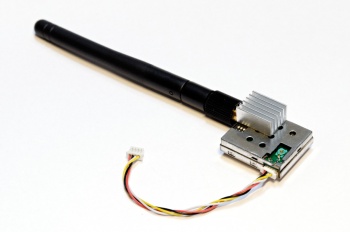

The downlink from the TBS Discovery to the ground station is provided by a small Lawmate 2.4GHz unit. It fits nicely on top of the frame in front away from the RC receiver to reduce RF noise on the RC link. Power is drawn from the TBS Core configured to output 5V.
- Lawmate Mods - few modifications to improve the performance (thermal mod, bandpass-filter)
FPV camera settings
Setup 2012-08-19
- Security Camera 2000 PZ0420 600TVL camera

The SC2000 PZ0420 600TVL camera provides an excellent picture for a reasonable price. There are only a few settings needed to be changed to improve the picture quality. Low light performance is great and quickly adapts to changing light conditions [2]. A detachable configuration/menu board is included.
Do a rest to defaults before setting the following options, mainly the brightness, contrast, sharpness and color levels.
- Exposure:
- Shutter speed: Auto
- Brightness: 065
- DWDR: On
- Level: 063
- White balance: ATW1
- Day and night: Color
- Image adjust:
- Lens Shade: On
- Level: 90
- Contrast: 090
- Sharpness: 031
- Display: LCD
- Gamma: 0.55
- Ped level: 023
- Color gain: 245
- Lens Shade: On
Perform fine-tuning at the flight location to lock-in the image quality even further.
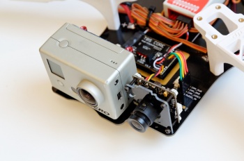
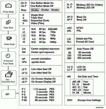
GoPro Hero1 settings
- GoPro Hero1 action camera

A GoPro is mounted in front of the frame to record high quality video during flight. To avoid getting the propellers in view, use the 1080p setting to get a 127 degree viewing angle (otherwise a 720p/170 degree view will capture the propellers).
The current settings for flight:
- One Button Mode: onF - Auto record after powering up off
- Start-up mode: F - Film/video - important
- Record mode: r5 - 1080p/30fps - important
- Metering: Cnt - Center weighted exposure - important
- Orientation: UP - Normal right side up
- Live feed: LFO - Live video feed on (not used)
- On-screen display: oSF - Text overlay on live feed off
- Auto photo capture: P5 - Capture photo every 5 seconds
- Blinking LED: bLO - Blinking red recording light on - important
- Beep: bP F - Button beeping off
- Video format: nSC - Video format NTSC for 60/30fps - important
- Delete last: LSt - Delete last photo on shutter press
- Power off: 60 - Automatically power off after 60 seconds
- LCD module: LCF - LCD module off (not installed)
- Date/time: <date> - Current date/time
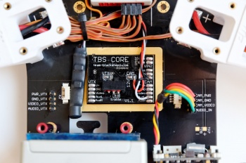
TBS Core setup
- TBS Core v1.1 - video- and power-controller
- Pin headers 2.0 mm pitch

Solder the Core onto the Discover frame, use the provided headers. Cut the headers to size and remove the unused pins. First solder the headers to the frame, use tape to hold the header in place, then install the Core on top of the headers. Make sure it does not touch the frame, only the headers. A helpful TBS Core install video is available from the TBS crew.
The Core provides a simple on-screen display which shows the instantaneous, total current consumption and flight time. In addition to that there is a RSSI signal strength indicator for the RC receiver control signal. Both need to be set up before they will function.
The following is a short summary of what's instructed in the TBS Core manual.
- Connect a video display to the video output and enable the RC control system
- Press the small button on the side of the TBS Core
- 'RSSI' should begin to blink on the display, hold the button for long periode to enter the RSSI menu
- A short press will change options, while a long press will confirm the action
- Select DIG to configure a PWM RSSI signal (EzUHF), another press will enter the max value range menu
- While keeping the transmitter close to the receiver, hold the button to configure the max value
- Then turn off the transmitter and set the min value by holding the button
- Now enable 100A current sensor by skipping through the menu until 'CURR' is displayed
- Hold the button to enter CURR and skip through to 100A, hold the button to confirm the action
- The OSD is now ready to be used!
Now start the motors in idle and move away from the receiver to check if the current and RSSI indicators show reasonable values.