Electric Bobby Car Build
| Electric Bobby Car | |
|---|---|
| |
| Overview | |
| Type: | Small electric vehicle |
| Build year: | 2019 |
| Base: | Big New Bobby Car |
| Layout: | Rear-wheel drive, front-wheel drive, all-wheel drive |
| Firmware: | larsmm hoverboard-firmware-hack-bbcar |
| Specifications | |
| Max speed: | 29km/h (turbo) |
| Range: | ~10km |
| Motors: | Four 350W BLDC permanent magnet motors with hall-sensors, 800W peak |
| Battery: | Lithium-ion 10S2P 4400mAh (10S-13S supported) |
| System voltage: | 36V |
| Charging: | External 42V 2A charger |
| Driving modes: | 4 - safe/slow/fun/power with turbo boost + reverse |
| Dimensions | |
| Wheelbase: | 394 mm |
| Width: | 330 mm |
| Length: | 575 mm |
| Weight: | X kg |
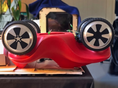
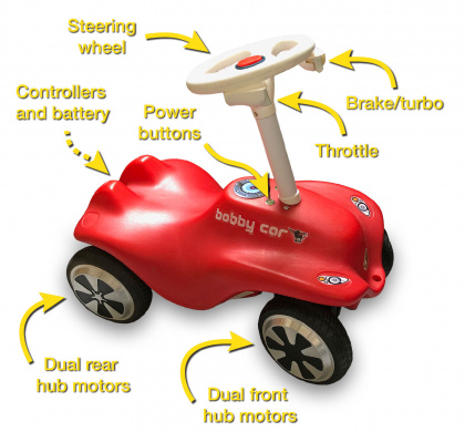
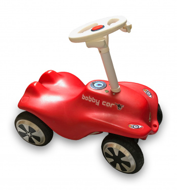
This is the Electric Bobby Car, or E-Bobby Car, motor upgrade build (not chronological log) using parts from two Hoverboards. The end result will have four motors (one per wheel), two Xbox 360 potentiometers as throttle and brake triggers, and two push buttons to turn on and off each motor controller independently for FWD, RWD, or AWD. Inside the Bobby Car all the equipment resides, e.g. the controllers, battery, and cabling, in addition to new parts to improve the strength of the base.
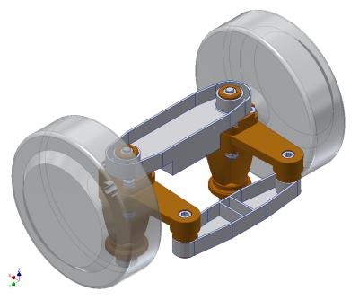
Most of the front wheel steering assembly had to be replaced by new 3D-printed parts. The same is true for the rear wheel base as it was replaced with an aluminum mounting plate.
The controllers was flashed to a new alternative firmware developed by Larsmm, which is a fork of the original work by NiklasFauth, rene-dev, and crinq. This firmware provides four driving modes with different speed, acceleration, turbo activation, and smooth acceleration and breaking ramps!
- Electric Bobby Car Hoverboard Upgrade - research page
- Electric Bobby Car CAD package - new parts in Inventor IPT, STEP and STL formats
Dec. 2019: ![]() Attending 36C3: Resource Exhaustion
Attending 36C3: Resource Exhaustion
Base preparation
Main equipment bay
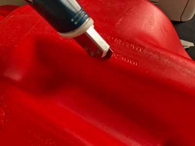
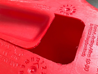
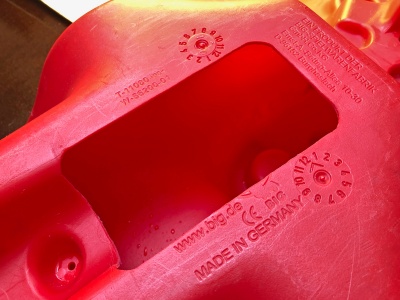
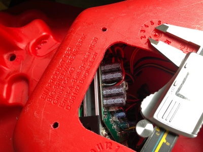
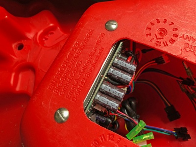
A slot had to by cut out of the bottom to allow internal access and functions as the main equipment bay. As the Bobby Car is made from polyethylene (PE-plastic) it is pretty easy to cut and handle.
The slot measures 78 x 148 mm, just enough to fit the controllers and battery. Rounded corners to minimize stress areas.
In the final stage it is covered by a see-through Lexan plate.
Rear wheel slots
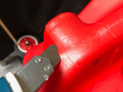
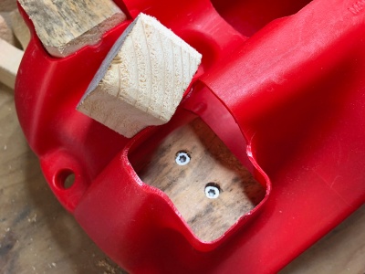
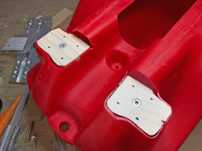
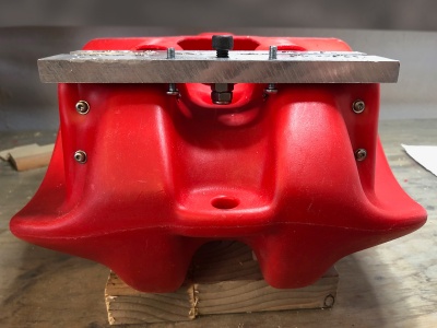
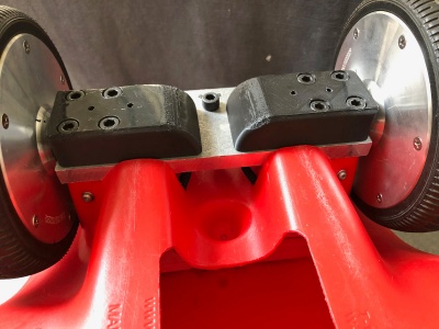
Two rear indentations were cut out to make space for a wooden structure which later would be used to mount a 12mm aluminium wheel plate. These were cut just at/below the stock axle hole and are at the same height as the new front wheels when installed, so the base would be level.
To judge the right cut height, it is an advantage to first prepare the rear wheel base and use it for make an educated approximation.
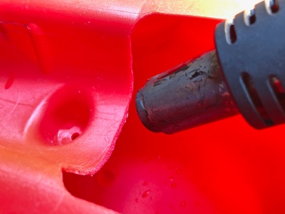
To remove sharp edges and to release stress areas, the edges were treated with a heat gun.
Rear wheel structure
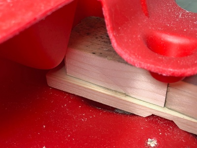
The internal rear wood structure consists of one cross beam and six smaller wood pieces stacked on top of each other. The load of the driver will be nicely distributed to the wheels and ground, easily increasing the max. driver weight to over 100kg!
Each wooden piece was fastened to the parent piece using wood screws, making sure to use a different screw pattern for each layer to avoid conflicts.
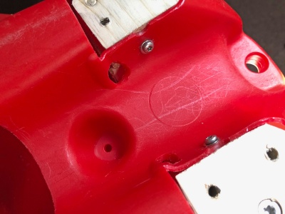
Mounting the wooden structure to the plastic base wall was done by nine 4 x 30mm wooden screws (pilot holes pre-drilled), linking each layer of the internal structure. Using washers to distribute the load as wide as possible. If the wheel touches the head of the screws, file them down a bit.
The end result was a very massive and solid base structure to mount the plate and wheels.
Rear wheels
All the stock parts of the Bobby Car front and rear wheels was removed, only a few parts of the steering was reused. Two Hoverboard wheel brackets and screws were also reused.
- Rear wheel parts included in the CAD package - all the parts in Inventor IPT, STEP and STL formats
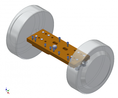
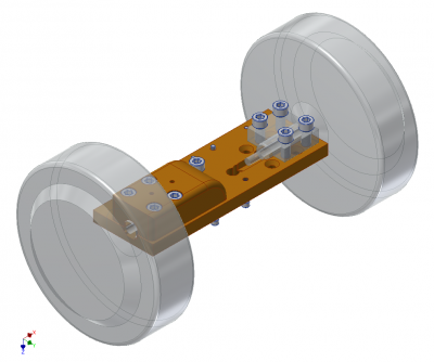
Wheel base plate
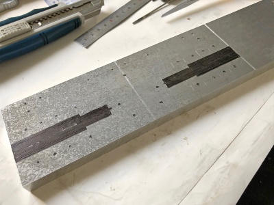
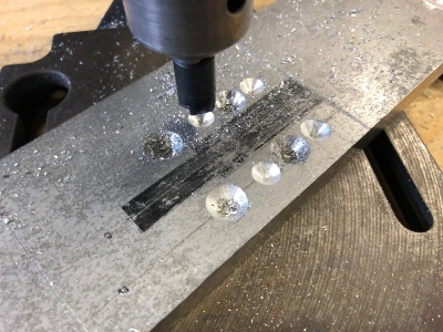
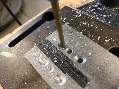
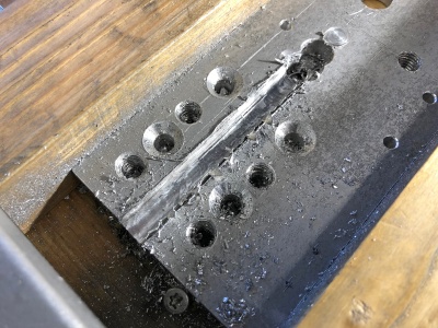
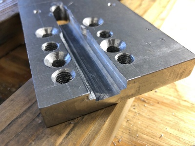
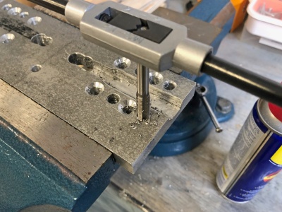
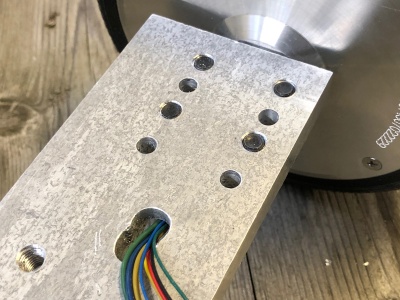
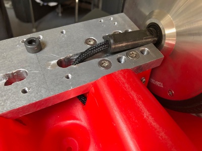
As much of the driver's weight will be over the rear wheels, the wheels had to be mounted on an strong 205x70x12mm 6061 aluminium plate. Slots and screw holes were routed and drilled/tapped out, respectively, using regular home/garage gear. Additional screw holes were added for future expansions, like a hook for a trailer, photo interrupter sensor, and lights.
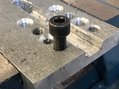
The plate was prepared by outlining the design on surface. The holes were first counter-sunk, then drilled. Sharp edges were deburred using the counter-sunk drill bit. Holes to fasten the plate to the wood structure were counter-sunk for a flush finish.
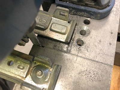
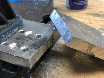
The plate was cut to length with a jig saw, at 205mm.
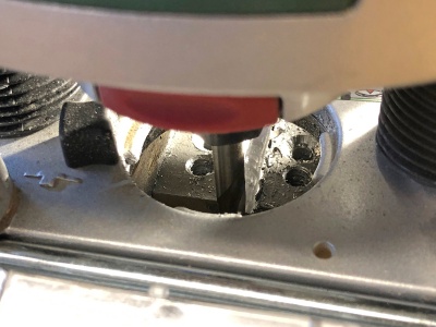
To cut out the wheel axle slots, a Bosch router with a HSS straight two flute Ø8mm milling cutter was used (see drawing for dimensions). I did 1-2mm cutting depth at each pass and multiple finer passes to end up at the final smooth finish. Used WD40 and low RPM on the router to avoid overheating the cutter.
The screw holes needed to be drilled with a pilot hole of Screw Diameter x 0.9 = Drill bit size, e.g. M8 x 0.9 = 7.2mm, or the closest one available (7mm). Then using a taper tap to gradually cutting out the required threads. Normal through holes use the required drill diameter, e.g. 8mm drill for 8mm hole.
Installing plate
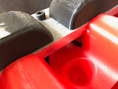
Once the wooden structure and plate was ready, pilot holes were drilled in the wooden structure (to relieve pressure and avoid cracking) and the plate was installed using 6 x 45mm counter-sunk wood screws. This provided a very stabel platform to mount the wheels.
Mounting wheels
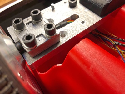
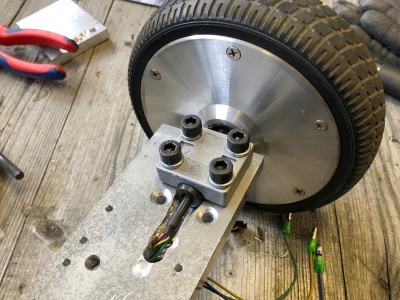
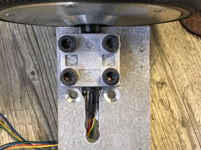
Both wheels are mounted to the base plate by sandwiching the axle between the stock Hoverboard bracket using the existing four M8 x 30mm screws. The tip of the screws won't protrude once fastened.
Axle cover
The axle and motor wires are directly exposed and could be damaged. A 3D-printed cover (include in the CAD package) screws in place over this area. Water drainage holes provided.
Rear wiring
The wiring coming from the motor was feed through the base plate and then inside the base through a small hole just underneath the front end of the wheel plate.
The wires were protected from abbreviation by a cable sleeve and heat shrink cover.
Front wheels
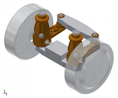
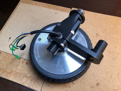
The front wheel assembly was modeled and new parts designed to incorporate the motors into the stock front wheel structure. Wheel clearance height was increase/raised by 10 mm to all the bigger radius Hoverboard wheels to fit (155mm vs 170mm).
All parts were designed/3D-printed (ABS) with strength as one of the main principles, primarily using long through screws and 70% infill to compress and distribute, respectively, much of the stresses experienced on the parts.
- Front wheel parts included in the CAD package - all the parts in Inventor IPT, STEP and STL formats
Full aluminium CNC parts or metal support inserts would be a future upgrade here.
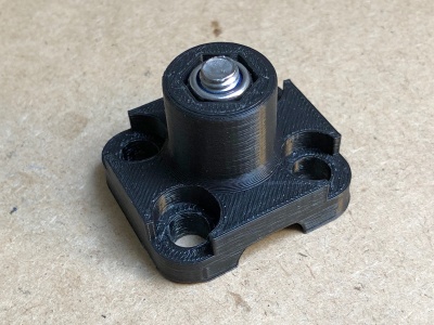
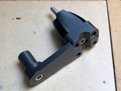
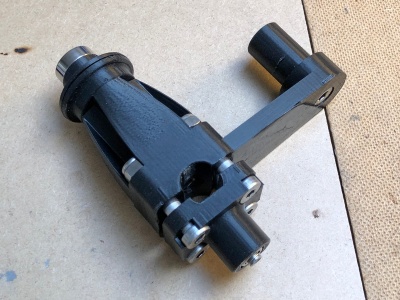
Steering wheel assembly
The assembly consists of four main parts and six screws along with six nuts to keep it all together. See the BOM for full break-down of the screw selection. A skateboard bearing lessens some of the pressure and tear on the upper steering joint.
Cross bracket
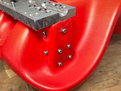
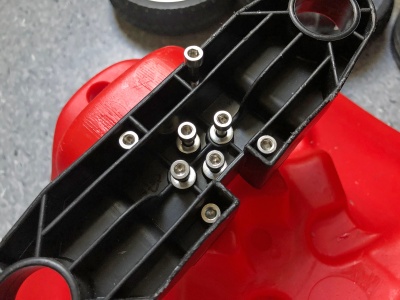
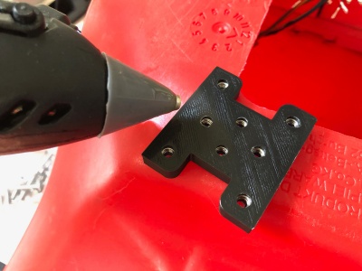
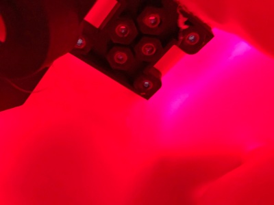
Both wheels are kept in alignment by the stock front cross bracket. This is screwed onto the base frame. The bracket had to be reinforced using eight M4 x 30mm screws which connect to a counter plate with the nuts inside the base, instead of the stock two threaded plastic screws. No washers on the four corner screws, for space reasons.
Front wiring
The wiring coming from the motor was feed through a small hole just in the middle of steering range motion to minimize cable stress/bending.
The wires were protected from abbreviation by a cable sleeve and heat shrink cover.
Steering
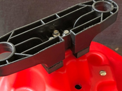
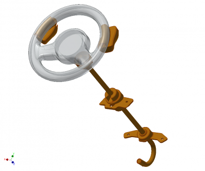
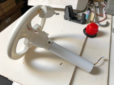
Much of the steering assembly was redesigned from ground, except for the steering wheel itself. Much work went into figuring out how the throttle and brake trigger would mount and wiring would be routed. Addition base reinforcement was also needed.
Base rod support
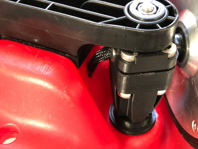
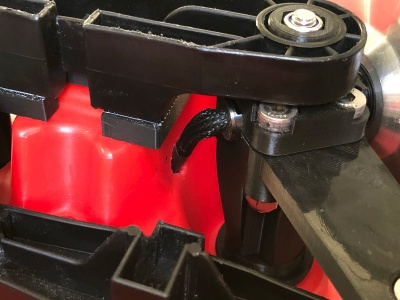
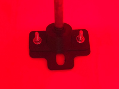
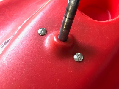
As there will be a lot of load on the steering rod, additional support had been added to the top and bottom side where the rod protrudes through the plastic base.
The top and bottom support brackets were fastened to the base using slotted M4 x 25 mm mushroom screws and nuts.
Inside both brackets are ID Ø10mm ball bearing to make the axial steering motion smoother.
Rod bending
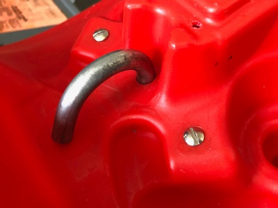
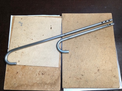
The new rod was based on the stock dimension and bend, just longer on one end to put the steering wheel at a comfortable position.
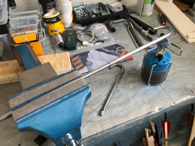
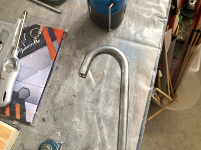
Using a Ø10mm stainless steel rod, one end was heated using a simple butane camping gas stove to make it pliable. Stuck it in vise and bent it to the approx. radius. Then put the entire bend into the vise and squeeze it into the right dimension, using the stock as a template. If the bent end is too long, saw it to the correct length. This took almost 2 hours.
Rod length and holes
The original rod was too short, so the steering wheel had to be raised and consequently the steering rod had to be lengthened by 155mm, the end rod length turned out to be 450mm.
Finding the best height can be done by trying the rod on the Bobby Car with the steering wheel next to it. Mark the spot and cut the rod - be sure to include the inserted length too.
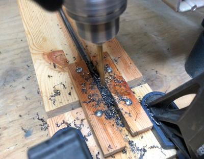
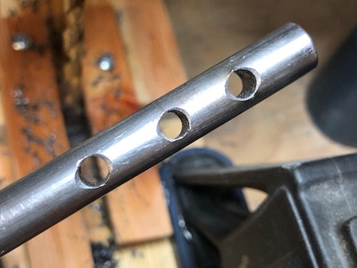
To allow for different steering wheel heights/accommodate more drivers, I made three different mounting holes, Ø5mm each. This also requires a through hole in the plastic on the steering wheel column. As I was going to use a small 300x300mm cotton cushion I included that in the measurement.
The holes were spaces in 15mm intervals:
- 15mm from end
- 30mm from end
- 45mm from end
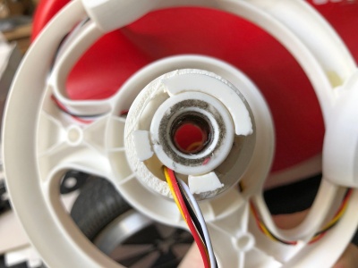
To keep the rod from falling through on assembly or pop out of the steering swing arm, an outer Ø32 x 140mm white PVC tube keeps the steering wheel at the correct position and protects the wiring going to the controller.
Throttle and brake
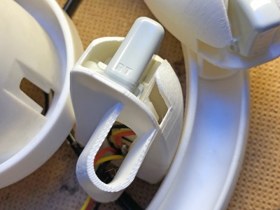
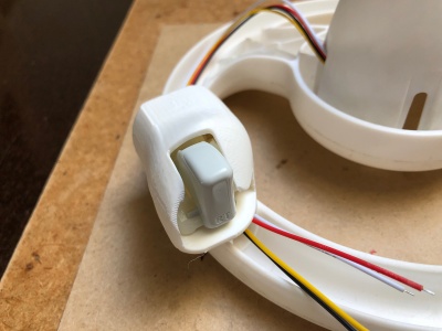
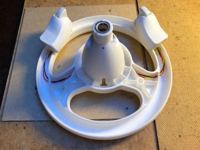
Using Larsm's method for the throttle and brake levers by mounting them on the front end (10:30 and 1:30 o'clock) on the steering wheel. A special 3D-printed holder keeps the trigger mechanism, 10kΩ potentiometer and support board in place. All put in place on the steering wheel using hot glue. An upgrade here would be a through screw.
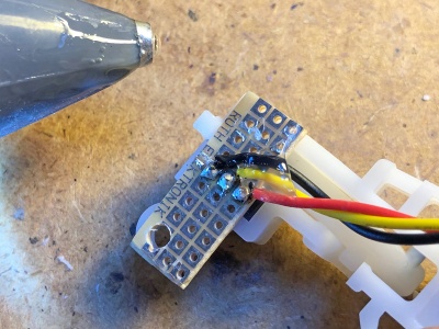
Wiring the potentiometer is simple, 3V3 (red), analog out (yellow, mid-pin), and ground (black). The wires are tucked away underneath the steering cup. When pressing the trigger the voltage rises gradually from 0V to 3V3 (in practice more like 0.6V to 2.6V because the pull-down resistor and the potentiometer not hitting its extreme range of motion.)
Steering wiring
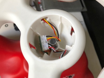
Both triggers connects to a modified break-out board - it just makes it easier to plug everything together using JST XH B4B connectors. It is located inside the steering wheel column. The real active break-out board is located next to the controllers.
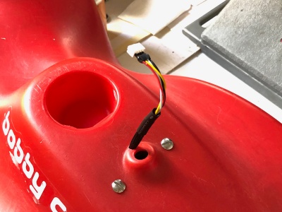
The lead was feed through a drilled hole in the steering wheel column and the lead from the break-out board comes out of a hole next close to the steering rod - making repairs easy.
Electronics
Break-out board
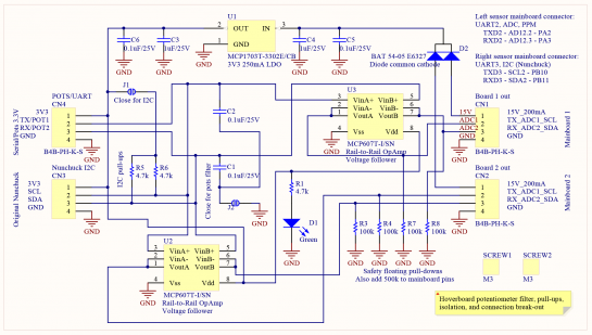
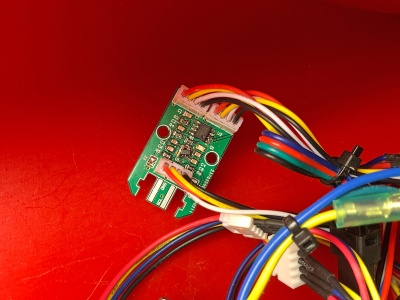
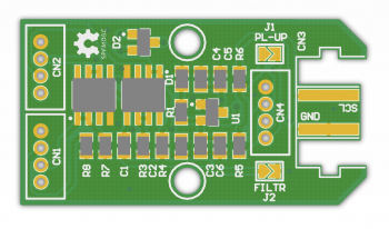
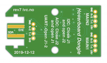
This is board makes it easier to finish the build. It easily connects the potentiometers and mainboards using JST XH B4B sockets, has analog signal filtering, a 3V3 250mAh LDO, I2C pull-ups (if required), and dual ADC voltage follower op-amp isolation. The isolation makes it possible for one driver board to be turned off without interfering with the other. The break-out tucks away inside the Bobby Car, next to the main boards.
Inspired by the Jan Henrik break-out boards.
Motor wiring
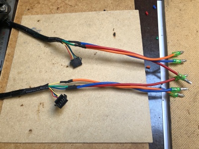
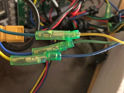
Connecting the front motors to controller is straight plug and play, but the rear main motor wires needed to be extended 10 cm to reach the controller. Simple cut-and-solder in 16 AWG extension wires, keeping the existing bullet connectors.
Note that if the motors will not turn correctly when throttle is applied, try to swap two of the leads and make sure every connection is solid.
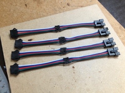
The thinner motor hall-effect wires were easily extended using custom made 15cm JST SM extension wires with connectors on each end.
A future upgrade would be to increase the gauge of the battery and motor wires, as they are already at their limits.
Mounting controllers
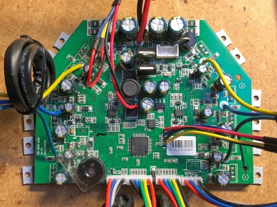
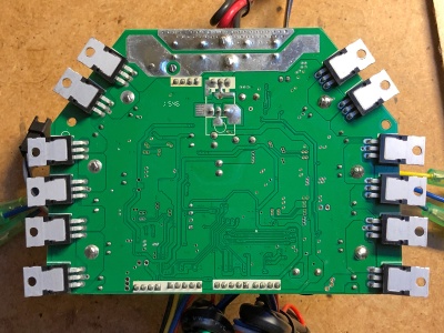
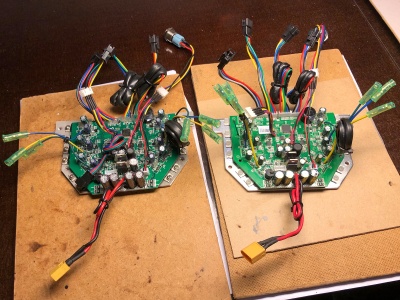
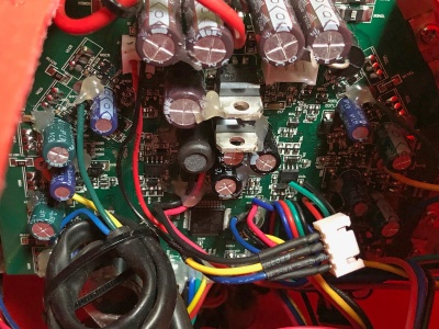
The controllers are essentially identical, except for slightly different caps, power transistors, and wiring method. Both are from Hoverboard productions in 2015. Both rock the same STM32F103 ARM Cortext-M3 MCU.
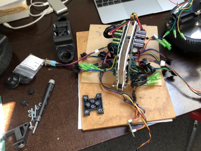
The controllers were mounted back-to-back using four M4 x 30mm screws and nuts with a stand-off spacer in-between, and installed vertically using a custom 3D-printed bracket and two slotted M5 x 16mm mushroom screws and nuts. A compact XT60 Y-splitter made out of two female and one male connector joins the two main power leads into one.
Battery
This build is using the stock 4.4Ah 10S2P 36V Lithium-ion battery from the Hoverboard. It is made of 20x Samsung ICR18650 3.7V 2200mAh cells, with a BMS built-in. The BMS (Battery Management System) takes care of overcharging, overcurrent protection, deep-discharge cut-off, and balancing the cells. A 12S 44.4V battery is supported by the mainboard components (even 13S), but that is left for a future upgrade.
The battery is kept secure by a hook-and-look strap around the battery and through two slots in a Lexan cover plate.
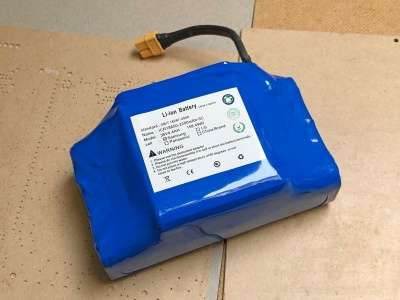 File:Electric bobby car build battery2.jpg
Power buttons
As this is a four motor, two controller setup, I wanted to have the possibility to power-on each controller independently. This would allow for FWD, RWD or AWD, depending on the occasion. This required the break-out board in order to isolate (op-amp voltage follower) the two controllers so they would not power each other or pull-down the throttle/brake signal when one of the controllers were powered down.
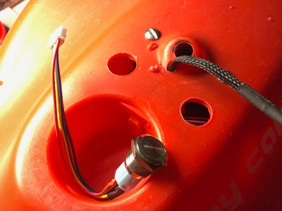
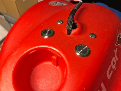
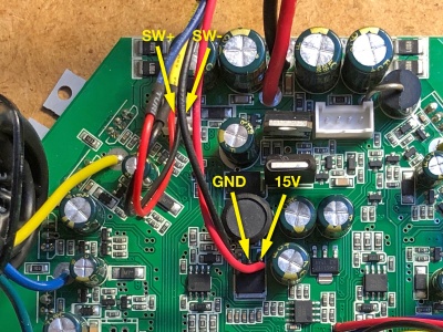
Two momentary green LED push non-latching buttons were prepared with a four-pin JST XH B4B connector. The corresponding socket was connected to the 15V regulator on the controller and power-on pins. A 2k resistor was put on the button LED power pin to lower the illumination. A Ø12mm hole was drilled and the buttons installed next to the steering rod.
Power harness and charging
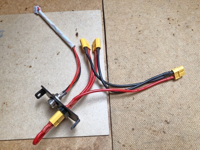
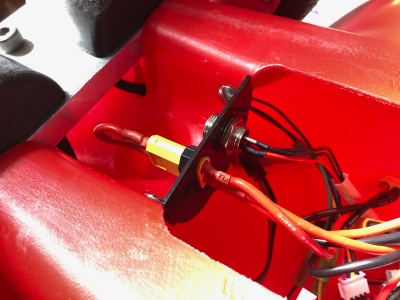
A 3D-printed bracket holds the disconnect plug (cuts all power) and the re-used charging port in place just rear of the equipment bay slot, by Fisch's inspiration. A Y-split harness was made to accommodate a future dual-battery setup, only one connector was used here. It connects four XT60 connectors and 10cm long 14AWG silicone power wires (in retrospect 10-12AWG is a better option.) The male end connects to the battery and the female to the compact Y-splitter from the mainboards, with a 60A fuse in-between.
The bracket was fastened using three shortened M4 x 25mm mushroom screws and nuts.
Note that you can still use the stock charging port, as it is a straight pass-through on the mainboard to the battery, with a simple charge-detect circuit for the MCU (not used in the new firmware). This charging-circuit should in theory be able to handle 12S and 13S setups.
Vibration protection
As there will be a fair about of vibration experienced by the main controllers, each major component (caps, regs, wires) was secured by hot glue - this is not the best compound as it does not grab very well, a future upgrade would be silicone potting compound.
Firmware
Configuration and calibrate
The larsmm Bobby Car optimized hoverboard firmware needed to be changed, calibrated and recompiled in order to be usable.
In Inc/config.h, assign the correct battery cell count under #define BAT_NUMBER_OF_CELLS 10. Use a multi-meter to measure the battery voltage, put the values in #define BAT_CALIB_REAL_VOLTAGE and #define BAT_CALIB_AD.
Calibrate the ADC inputs #define ADC1_MIN #define ADC1_MAX #define ADC2_MIN #define ADC2_MAX under #define CONTROL_ADC, using the serial debugging output (see next section). Press the triggers and note the max. and min. values. The STM32 ADCs are 12-bit, meaning 0 to 4096. For this build the calibrated range was approx. 720 to 3790, which corresponds to 0.6V to 2.6V.
If the wheels rotate the wrong direction, comment out //#define INVERT_R_DIRECTION and //#define INVERT_L_DIRECTION. Note that you will end up with two firmware versions, one for each controller.
To adjust the reverse speed, adjust the ...(ADC2_DELTA / 280.0f)... snippet in Src/main.c for each driving mode. Higher values increases the speed, try 400.0f to 800.0f.
Compile firmware
To compile the firmware I used an Arch CLI VMWare image from OSBoxes.org to set up the ARM toolchain.
pacman -S arm-none-eabi-gcc arm-none-eabi-newlib autoconf automake bison confuse coreutils cower diffutils expac fakeroot flex gcc gcc-libs gettext git glibc groff gzip libtool licenses m4 make man-db nano openocd patch perl pkgconf s-nail sed stlink texinfo util-linux vi
git clone https://github.com/larsmm/hoverboard-firmware-hack-bbcar
cd hoverboard-firmware-hack-bbcar
nano Inc/config.h
make
The new firmware will reside in build/hover.bin
Debugging
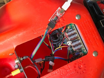
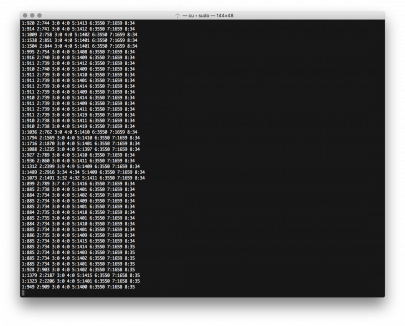
In Inc/config.h you can enable debugging output #define DEBUG_SERIAL_USART3 #define DEBUG_SERIAL_ASCII to enable an serial UART console on the right sensor board connector. Each board got its own debugging connector, as seen in the photo. Connect an USB-to-serial adapter to the TX, RX, and GND pins - 3V3 not needed.
This console outputs a comma separated string of the current operating parameters, as listed.
Example: 1:812 2:723 3:0 4:0 5:1547 6:3903 7:1650 8:36
1:ADC1, TX, right, forward2:ADC2, RX, left, brake/reverse3:Output speed: 0-10004:Output speed: 0-10005:For battery voltage calibration6:For verifying battery voltage calibration7:For board temperature calibration8:For verifying board temperature calibration
Flash firmware
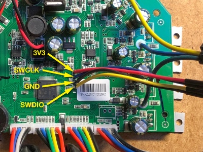
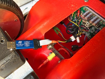
The Hoverboard controller board exposes the SWD-programming port. Only three wires needed to be soldered in order to flash the mainboard. Each board got its own programming connector, as seen in the photo.
| Pin | Board | Programmer | Wire color (in photo) | Note |
|---|---|---|---|---|
| 1 | DIO | SWDIO | Yellow wire | - |
| 2 | GND | GND | Black wire | - |
| 3 | CLK | SWCLK | Blue wire | - |
| 4 | 3V3 | 3V3 | Red wire | Leave unconnected, 3V3 provided by board |
Make sure the battery and power-button is connected as this is required to flash. Connect the ST-Link V2 Mini programmer to the mainboard.
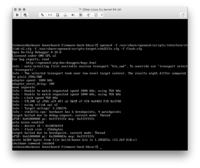
Power off, press and hold the power-button while restoring power, keep holding and executing the following commands. It only takes a few seconds. If you get an error were openocd detects the ST-Link but not the mainboard, check the power-button and that you hold it during the entire process.
Unlock MCU:
openocd -f /usr/share/openocd/scripts/interface/stlink-v2.cfg -f /usr/share/openocd/scripts/target/stm32f1x.cfg -c "init" -c "reset halt" -c "stm32f1x unlock 0"
Flash MCU:
openocd -f /usr/share/openocd/scripts/interface/stlink-v2.cfg -f /usr/share/openocd/scripts/target/stm32f1x.cfg -c "init" -c "reset init" -c "halt" -c "flash write_image erase build/hover.bin 0x8000000" -c "shutdown"
Usage
Using the Electric Bobby Car is pretty easy. There are two triggers for throttle and brake, two buttons to enable/start-up the front and/or rear motors, and a steering wheel. After acceleration and releasing the triggers (no input), the controller will exponential brake to a halt.
| Input function | Control output |
|---|---|
| Right trigger/ADC1 | Acceleration/throttle |
| Left trigger/ADC2 | Brake/turbo activation |
| Right power button | Front controller/motors |
| Left power button | Rear controller/motors |
| Steering wheel | Turn the front wheels |
When the controller start up, it will beep according to the active driving mode.
| Trigger | Beep(s) | Driving mode | Max. speed | Turbo |
|---|---|---|---|---|
| Left trigger | 1 beep | Mode 1 - Safe | 3 km/h | No |
| No trigger, default | 2 beep | Mode 2 - Slow | 6 km/h | No |
| Right triggger | 3 beep | Mode 3 - Normal | 12 km/h | No |
| Left and right trigger | 4 beep | Mode 4 - Fast | 22 km/h | Yes, L+R trigger 29 km/h |
Areas of improvements
- Steering wheel mounting to steering rod, less slack
- Battery voltage increase, 10S to 12S
- Power cable upgrade, 14AWG to 10AWG
- Steering wheel assembly upgrade, from ABS to Aluminium
- Steering wheel display, showing battery and driving details
- Front beams and rear red brake lights, traffic ready 😁
BOM
CAD models:
- Electric Bobby Car CAD package - Inventor IPT, STEP and STL formats
General parts
| Quantity | Description | Designation |
|---|---|---|
| 1x | Big New Bobby Car | Main base |
| 2x | Xbox 360 Game controller 10kΩ potentiometer | Throttle and brake triggers |
| 2x | Hoverboard with STM32 MCU | Wheels, controllers, batteries and misc. |
| 1x | ST Link V2 compatible programmer | Flash new firmware |
| 1x | FTDI USB to TTL Serial Adapter Module | Debugging console |
| 1x | Aluminium 6061 205x70x12mm plate | Rear wheel plate |
| 1x | Several two-by-four wood pieces | Rear wheel structure |
| 1x | Round Stainless Steel Rod Ø10mm x 45cm alt. | Steering wheel rod |
| 1x | Plastic PVC Ø32mm x 50cm tube alt. | Steering wheel height and wire protection |
| 4x | JST SM-2.54 22AWG Wire Male and Female Connectors | Hall-effect extension cable |
| 1x | XT60 60A Female Male connectors | Power plug and power cable |
| 1x | Silicone Wire 14AWG red Hobbyking | Power cable |
| 1x | Silicone Wire 14AWG black Hobbyking | Power cable |
| 2x | Deep Groove Ball Bearing 608ZZ ID Ø8mm | Front upper wheel join load distribution |
| 2x | NMB Steel Bearing Motor Grade Bearing ID Ø10mm | Steering rod lower load distribution |
Screws
References
- Larsm Allrad e-Bobby Car - great write up and custom firmware fork
- Niklas Fauth Hoverboard firmware hack - original firmware (Twitter FauthNiklas and JanHenrikH)
- CCC GPN18 HowTo: Moving Objects - great talk
- Build Instruction: TranspOtter - Another build, lots of helpful pictures
- Fisch's detailed E-Bobby Car build log - great documentation of the assembly
- Fisch's trailer build - trailer for the Bobby Car
- Jan Henrik breakout boards - PCBs for easy connection to serial and Nunchuck
- Peter Pötzi Electric Bobby-Car - Blue Bobby Car with LCD steering display
- cloidnerux AT32F403RCT6 firmware - for newer mainboards with the AT32F403RCT6 MCU
