MakerBot: Difference between revisions
| Line 28: | Line 28: | ||
== Symbols == | == Symbols == | ||
All the components below has been compiled into a Frizing library to be used for prototyping, the connection-points has bin omitted. The original illustrator files | All the components below has been compiled into a Frizing library to be used for prototyping, the connection-points has bin omitted. The original illustrator files are also available. | ||
'''Packages:''' | '''Packages:''' | ||
Revision as of 10:26, 11 September 2011
The MakerBot is an open source 3D-printer. Great for experimenting with designs and small manufacturing. The latest model, Thing-O-Matic, has improved printing accuracy and expanded electronics platform.
I don't currently own a Makerbot.
Schematics
Electronics
On the Thing-O-Matic all the electronics are neatly hidden away under the build platform, including the power-supply.
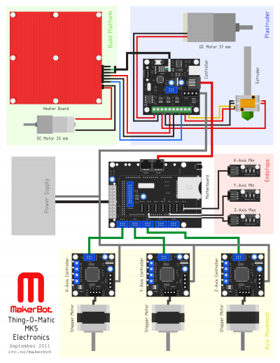
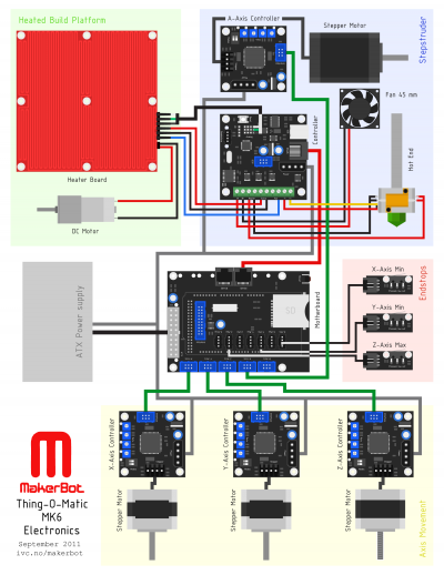
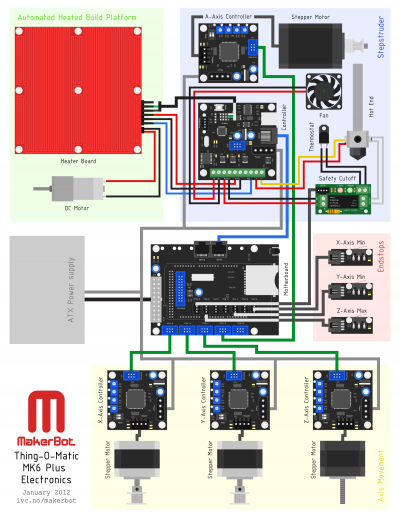
The electrical connections is shown in the overview image below. It shows all the components and how they're connected. For more details and photos of the assembly, check the official Thing-O-Matic electronics installation pages.
Schematic:
- Download Thing-O-Matic MK5 electronics schematic - PDF vector version
- Download Thing-O-Matic MK6 electronics schematic - PDF vector version
- Download Thing-O-Matic MK6 Plus electronics schematic - PDF vector version
For PNG versions, check the images below. Hi-res versions are available when you click through to the final link.
MK5
MK6
MK6 Plus
Symbols
All the components below has been compiled into a Frizing library to be used for prototyping, the connection-points has bin omitted. The original illustrator files are also available.
Packages:
- Download MakerBot Thing-O-Matic MK5 vector files - Illustrator, PDF, PNG versions
- Download MakerBot Thing-O-Matic MK6 vector files - Illustrator, PDF, PNG versions
- Download MakerBot Thing-O-Matic MK6 Plus vector files - Illustrator, PDF, PNG versions
- Download MakerBot Thing-O-Matic Frizing library - Open with Fritzing
Motherboard
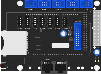
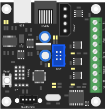
The main board is mounted together with a Arduino-controller. An external USB-interface allow commands to be sent via [1] ReplicatorG] and a SD-card slot can be used to load files to be printed in sequence locally. A row of connectors hooks up the stepper motor controllers, extruder controller, and endstops.
Extruder
This board has inputs from the thermalcouple temperature measuring probe, high-power MOSFET to drive current the main heater to melt plastic and heat the assembly board. Auxiliary connections for controlling the automated assembly plate and heat sensor for the board temperature control.
On top of the extruder is the feed for the plastic, driven by a DC-motor from the extruder controller. The heat element is a long piece of metal tube to keep the heat and melting process even. Two heat resistors exerts heat onto the main metal block before the plastic is extruded through a narrow nozzle. The thermocouple is mounted on the main block.
On the newer MK6 and MK6 Plus models the DC-motor is swapped in favor of a more precise stepper motor. The heater element is also upgraded to a custom made heater cartridge coupled with a safety cutoff board.
Stepper Controller
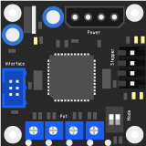
To drive the stepper motors, a controller can control the motion of the axis down to an accuracy of 1.8 degrees per step. The operation can be fine tuned using 4 potentiometers on the controller. Two dip-switches determine the type of stepper-motor that will be attached.
End stops
Each axis has an end-stop to signal when its at the farthest/closes point in its range.
Heaterboard
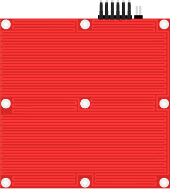
To keep the plastic from shrinking during the printing process, the base where the object sits is heated by a copper maze on the board. A thermistor underneath is monitoring the temperature. On the automated model the base can roll out when the object is finished.
