MakerBot Replicator 1 Adapting A4988 Replacement Driver
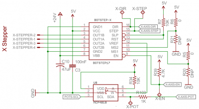
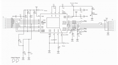
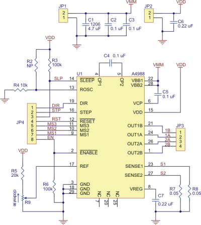
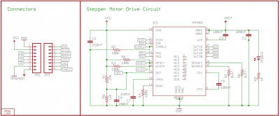
The BotStep17 driver board on the MakerBot Replicator 1 (and 2/2X) uses the A4982 stepper drive IC. It is hard to get replacement driver boards for this model. An popular alternative which is used by many other 3D printers is the A4988. It can be adapted to work with the MakerBot 3D printers.
Differences
- A4988 includes 1/8th step resolution, although the MakerBot firmware utilizes 1/16th resulution
- A4982 boards has the Vref pin exposed on the pin headers
- Most A4988 boards has the pin-out flipped-around, so the pins stick out the other way from what the MakerBot is using
- A4982 boards has a better thermal design with exposed copper surface
- All A4988 board set the current limit by turning a trimpot, while A4982 on MakerBot is done digitally
Digipot values
The Vref is adjusted by changing the lower-side of a voltage divider.
Vref = 5V*(0..5k/(10k+0..5k))
Where 0..5k is adjusted in steps via software (MakerWafe prefs) between 0 to 127 (7-bit)
For example, N is set to 118:
Vref = 5V*(5k*(118/127)/(10k+(5k*(118/127)))) = 1.59V
Adapting A4988 boards
MakerBot Replicator MightyBoard expects:
- VDD 5.0V supply voltage
- Imax 833mA per coil
- Stepper resolution 1/16th
- Fixed Time-Off to 30uS / Mixed decay
Flipping around the pin headers
The pin header is on the opposite side of what the Makerbot expects.
- Unsolder all the pins from the driver board
- Do this by carefully removing the plastic shoulder and removing the solder using a solder sucker pump
- Clean all the vias and widen them using a small drill bit if necessary
- Prepare two new 8-pin 2.54mm pin header strips
- Remove the MS3-pin on all the headers
- Solder the pin header on with the pins sticking out from the component side, like on the BotStep17
- Use a short piece of wire and solder it between MS3 and VDD pin on the flat surface of the driver board
Adjusting trimpot current limit
- Check what the Rsense resistor value is on the board (or schematic), usually either 0.27/0.2/0.05 Ohms - the MakerBot sets the current limit to 830mA (0.830A) and driven by 24V for good amount of torque.
- Find the Vref you need using this equation Vref=(8*Rsense)*0.830, for instance 0.2 Ohm gives (8*0.2)*0.833=1.33V
- Use a multimeter to measure the total resistance of the trimpot between the pads opposite of the third pad, Rpot
- Calculate the desired Radjust resistance to tune for by putting the Rpot value into the equation Radjust=(20+Rpot)*1.33/5, for instance 8.2k gives (20+8.2)*1.33/5=7.5 or 7.5k Ohms to adjust for
- Use the multimeter to measure the resistance between ground and the top of the trimpot, adjust the screw until it matches the calculated value
- Done, insert into the Mightyboard with the DIR and GND pins facing the stepper motor connector
Calculating current
To check, the Imax will be:
Imax = Vref/(8 x Rsense)
And using Vref 1.33V and 0.2Ohm:
Imax = 1.33/(8 x 0.27) = 0.831A (831mA)
The A4982 and A4988 can handle approx. 1A without any heatsink or active cooling, and up to 2A with cooling.


