Uncategorized files
From ivc wiki
Jump to navigationJump to search
Showing below up to 500 results in range #251 to #750.
View (previous 500 | next 500) (20 | 50 | 100 | 250 | 500)
 Downgrader installed J2B1.jpg 640 × 480; 190 KB
 Downgrader installed JTAG.jpg 640 × 480; 188 KB
 Downgrader installed POST.jpg 640 × 480; 179 KB
 Downgrader installed overview.jpg 640 × 480; 177 KB
 Dummy camera assemble enclosure.jpg 1,600 × 1,200; 383 KB
 Dummy camera box.jpg 1,600 × 1,200; 490 KB
 Dummy camera cable installed.jpg 1,600 × 1,200; 642 KB
 Dummy camera cable notch.jpg 1,600 × 1,200; 492 KB
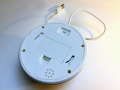 Dummy camera complete bottom.jpg 1,600 × 1,200; 408 KB
 Dummy camera complete top.jpg 1,600 × 1,201; 427 KB
 Dummy camera dome quality.jpg 1,600 × 1,200; 465 KB
 Dummy camera overview.jpg 1,600 × 1,200; 403 KB
 Dummy camera raspberry pi camera cable close-up.jpg 1,600 × 1,200; 653 KB
 Dummy camera raspberry pi camera inside cover installed.jpg 1,600 × 1,200; 419 KB
 Dummy camera raspberry pi camera installed.jpg 1,600 × 1,200; 507 KB
 Dummy camera raspberry pi camera mount part.jpg 1,600 × 1,200; 368 KB
 Dummy camera raspberry pi holder part.jpg 1,600 × 1,200; 573 KB
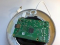
 Dummy camera raspberry pi installed.jpg 1,600 × 1,200; 703 KB
 Dummy camera web administration.png 1,279 × 1,000; 356 KB
 Dump32 Compile and Start.png 640 × 480; 45 KB
 Dump32 Finished and List.png 640 × 480; 52 KB
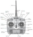 Dx7 control layout.png 702 × 780; 266 KB
 Eee Network Admin.png 286 × 196; 19 KB
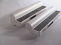 Eee battery comparison.jpg 640 × 480; 89 KB
 Eee battery mugen.jpg 640 × 480; 100 KB
 Eee battery org.jpg 640 × 480; 96 KB
 Eee bios chip.jpg 640 × 480; 182 KB
 Eee bluetooth adapter.jpg 640 × 480; 82 KB
 Eee bluetooth box.jpg 640 × 480; 104 KB
 Eee bluetooth devicemanager.png 496 × 248; 15 KB
 Eee bluetooth mounted.jpg 640 × 480; 137 KB
 Eee bluetooth mounted side.jpg 640 × 480; 176 KB
 Eee bluetooth open back.jpg 640 × 480; 101 KB
 Eee bluetooth open front.jpg 640 × 480; 91 KB
 Eee bluetooth wires.jpg 640 × 480; 146 KB
 Eee cardreader bay.jpg 640 × 480; 149 KB
 Eee cardreader box.jpg 640 × 480; 99 KB
 Eee cardreader chip.jpg 476 × 356; 85 KB
 Eee cardreader height.jpg 640 × 480; 167 KB
 Eee cardreader open.jpg 640 × 480; 89 KB
 Eee cardreader positioning.jpg 640 × 480; 186 KB
 Eee cardreader sideways.jpg 640 × 480; 179 KB
 Eee cardreader stripped.jpg 640 × 480; 85 KB
 Eee cardreader top.jpg 640 × 480; 186 KB
 Eee clear cmos.jpg 350 × 263; 50 KB
 Eee diagram back.jpg 1,148 × 800; 304 KB
 Eee diagram front.jpg 1,160 × 800; 325 KB
 Eee eeectrl systray.png 369 × 300; 37 KB
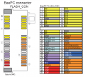 Eee flash con pinout.png 518 × 466; 53 KB
 Eee flashdrive box.jpg 640 × 480; 165 KB
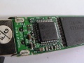 Eee flashdrive controller.jpg 640 × 480; 177 KB
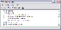 Eee flashdrive devicemanager.png 496 × 248; 16 KB
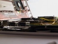 Eee flashdrive height.jpg 640 × 480; 165 KB
 Eee flashdrive mounted.jpg 640 × 480; 183 KB
 Eee flashdrive nand.jpg 640 × 480; 170 KB
 Eee flashdrive newloc mounted.jpg 640 × 480; 186 KB
 Eee flashdrive newloc mounted side.jpg 640 × 480; 180 KB
 Eee flashdrive open back.jpg 640 × 480; 94 KB
 Eee flashdrive open front.jpg 640 × 480; 93 KB
 Eee flashdrive overview.jpg 640 × 480; 187 KB
 Eee fmtransmitter adapter.jpg 640 × 480; 156 KB
 Eee fmtransmitter antenna mounted.jpg 640 × 480; 179 KB
 Eee fmtransmitter antenna ready.jpg 640 × 480; 170 KB
 Eee fmtransmitter antenna side.jpg 640 × 480; 158 KB
 Eee fmtransmitter audio motherboard.jpg 640 × 480; 175 KB
 Eee fmtransmitter back.jpg 640 × 480; 167 KB
 Eee fmtransmitter box.jpg 640 × 480; 173 KB
 Eee fmtransmitter buttons.jpg 640 × 480; 178 KB
 Eee fmtransmitter coaxcable.jpg 480 × 640; 81 KB
 Eee fmtransmitter front.jpg 640 × 480; 180 KB
 Eee fmtransmitter height.jpg 640 × 480; 188 KB
 Eee fmtransmitter open.jpg 640 × 480; 156 KB
 Eee fmtransmitter side.jpg 640 × 480; 178 KB
 Eee fmtransmitter stripped.jpg 640 × 480; 109 KB
 Eee fmtransmitter top.jpg 640 × 480; 172 KB
 Eee gps antenna crystal.jpg 640 × 480; 94 KB
 Eee gps antenna mounted.jpg 640 × 480; 162 KB
 Eee gps antenna mounted side.jpg 640 × 480; 171 KB
 Eee gps antenna soldered.jpg 640 × 480; 190 KB
 Eee gps cable insulation.jpg 640 × 480; 179 KB
 Eee gps cable joint.jpg 640 × 480; 147 KB
 Eee gps chassis fit.jpg 640 × 480; 168 KB
 Eee gps chassis space.jpg 640 × 480; 181 KB
 Eee gps devicemanager.png 496 × 248; 16 KB
 Eee gps display after.jpg 640 × 480; 182 KB
 Eee gps display before.jpg 640 × 480; 182 KB
 Eee gps height.jpg 640 × 480; 161 KB
 Eee gps kit.jpg 640 × 480; 107 KB
 Eee gps mounted.jpg 640 × 480; 174 KB
 Eee gps overview.jpg 640 × 480; 149 KB
 Eee gps stripped back.jpg 640 × 480; 100 KB
 Eee gps stripped front.jpg 640 × 480; 137 KB
 Eee hdtune adatasdhccard 8gb.png 570 × 464; 39 KB
 Eee hdtune adatasdhccard 8gb 900mhz.png 570 × 464; 39 KB
 Eee hdtune siliconmotion 4gb.png 570 × 464; 41 KB
 Eee hdtune siliconmotion 4gb 900mhz.png 570 × 464; 41 KB
 Eee hdtune voyagergt 4gb.png 570 × 464; 39 KB
 Eee hdtune voyagergt 4gb 900mhz.png 570 × 464; 39 KB
 Eee heatsink artic silver.jpg 640 × 480; 93 KB
 Eee heatsink chips clean.jpg 640 × 480; 176 KB
 Eee heatsink copper plates.jpg 640 × 480; 154 KB
 Eee heatsink copper plates aligned.jpg 640 × 480; 185 KB
 Eee heatsink copper plates kapton.jpg 640 × 480; 154 KB
 Eee heatsink dimensions.gif 443 × 215; 3 KB
 Eee heatsink keyboard shielding.jpg 640 × 480; 78 KB
 Eee heatsink lid keyboard.jpg 640 × 480; 65 KB
 Eee heatsink location animation.gif 400 × 280; 118 KB
 Eee heatsink old thermal pads.jpg 640 × 480; 174 KB
 Eee heatsink old thermal pads moved.jpg 640 × 480; 165 KB
 Eee heatsink thermal compound overview.jpg 640 × 480; 179 KB
 Eee heatsink thermal compound processor.jpg 640 × 480; 163 KB
 Eee heatsink top casing assembled.jpg 640 × 480; 164 KB
 Eee lcd modelnumber.jpg 640 × 480; 170 KB
 Eee linux ubuntu cover.jpg 900 × 640; 126 KB
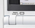 Eee magnet lid.jpg 430 × 350; 37 KB
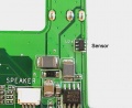 Eee magnet sensor.jpg 430 × 350; 47 KB
 Eee memory 910gml.png 556 × 112; 13 KB
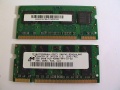 Eee memory modules back.jpg 640 × 480; 141 KB
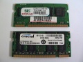 Eee memory modules front.jpg 640 × 480; 142 KB
 Eee mini pcie removed.jpg 285 × 507; 86 KB
 Eee modem connector.jpg 640 × 480; 99 KB
 Eee modem devicemanager.png 496 × 248; 16 KB
 Eee modem driverfolder.png 448 × 281; 31 KB
 Eee modem driverinf.png 472 × 266; 15 KB
 Eee modem height.jpg 640 × 480; 149 KB
 Eee modem mounted.jpg 640 × 480; 179 KB
 Eee modem signals header.jpg 640 × 480; 173 KB
 Eee modem signals mdc.jpg 640 × 480; 168 KB
 Eee modem wires.jpg 640 × 480; 183 KB
 Eee open bottom.jpg 640 × 480; 122 KB
 Eee open display.jpg 640 × 480; 90 KB
 Eee open front.jpg 640 × 480; 131 KB
 Eee overclock 3dmark.png 516 × 345; 48 KB
 Eee overclock cpuz.png 390 × 442; 25 KB
 Eee overclock cpuz 1101mhz.png 390 × 441; 25 KB
 Eee overclock cpuz 1101mhz mainboard.png 390 × 442; 18 KB
 Eee overclock cpuz 1101mhz memory.png 390 × 442; 19 KB
 Eee overclock cpuz 1101mhz spd.png 390 × 442; 21 KB
 Eee overclock memset pc4200.png 287 × 577; 18 KB
 Eee overclock setfsb.png 518 × 264; 20 KB
 Eee overclock setfsb 1101mhz.png 518 × 264; 20 KB
 Eee overclock superpi.png 512 × 305; 14 KB
 Eee overview complete.jpg 640 × 480; 108 KB
 Eee overview display.jpg 640 × 480; 168 KB
 Eee overview march08 display.jpg 640 × 480; 107 KB
 Eee overview march08 motherboard bottom.jpg 640 × 480; 185 KB
 Eee overview march08 motherboard bottom closeup1.jpg 640 × 480; 176 KB
 Eee overview march08 motherboard bottom closeup2.jpg 640 × 480; 185 KB
 Eee overview march08 motherboard bottom closeup3.jpg 640 × 480; 188 KB
 Eee overview motherboard bottom.jpg 640 × 480; 164 KB
 Eee overview motherboard bottom1.jpg 640 × 480; 184 KB
 Eee overview motherboard bottom2.jpg 640 × 480; 189 KB
 Eee overview motherboard bottom3.jpg 640 × 480; 169 KB
 Eee overview motherboard top.jpg 640 × 480; 182 KB
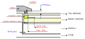
 Eee power signal diagram bottom.jpg 1,579 × 1,100; 549 KB
 Eee power signal diagram top.jpg 1,596 × 1,100; 537 KB
 Eee powerswitch 10dip assembled.jpg 640 × 480; 103 KB
 Eee powerswitch 10dip mounted.jpg 640 × 480; 184 KB
 Eee powerswitch 10dip mounted front.jpg 640 × 480; 185 KB
 Eee powerswitch 10dip old new.jpg 640 × 480; 183 KB
 Eee powerswitch 5v point1.jpg 640 × 480; 173 KB
 Eee powerswitch 5v point2.jpg 640 × 480; 180 KB
 Eee powerswitch 5v point3.jpg 640 × 480; 173 KB
 Eee powerswitch bay.jpg 640 × 480; 189 KB
 Eee powerswitch parts.jpg 640 × 480; 88 KB
 Eee setfsb.png 518 × 264; 24 KB
 Eee sound recorder.png 327 × 286; 18 KB
 Eee ssd intel.jpg 747 × 518; 164 KB
 Eee temper.jpg 547 × 503; 101 KB
 Eee temperature copper plates sample 1 mobmeter.png 423 × 336; 7 KB
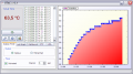 Eee temperature copper plates sample 1 utac.png 725 × 405; 46 KB
 Eee temperature copper plates sample 2 mobmeter.png 423 × 336; 6 KB
 Eee temperature copper plates sample 2 utac.png 725 × 405; 45 KB
 Eee temperature copper plates sample 3 mobmeter.png 423 × 336; 6 KB
 Eee temperature copper plates sample 3 utac.png 725 × 405; 45 KB
 Eee temperature sensor bottom.jpg 640 × 480; 107 KB
 Eee temperature sensor box.jpg 640 × 480; 102 KB
 Eee temperature sensor mounted.jpg 640 × 480; 180 KB
 Eee temperature sensor mounted overview.jpg 640 × 480; 176 KB
 Eee temperature sensor top.jpg 640 × 480; 101 KB
 Eee temperature superpi.png 512 × 196; 12 KB
 Eee temperature thermal pads sample 1 mobmeter.png 423 × 336; 6 KB
 Eee temperature thermal pads sample 1 utac.png 725 × 405; 45 KB
 Eee temperature thermal pads sample 2 mobmeter.png 423 × 336; 7 KB
 Eee temperature thermal pads sample 2 utac.png 725 × 405; 43 KB
 Eee temperature thermal pads sample 3 mobmeter.png 423 × 336; 6 KB
 Eee temperature thermal pads sample 3 utac.png 725 × 405; 38 KB
 Eee touch screen overlay.png 496 × 229; 11 KB
 Eee touch screen resistive.gif 469 × 151; 15 KB
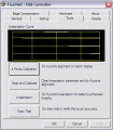 Eee touchkit.png 401 × 459; 18 KB
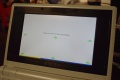 Eee touchkit calibration.jpg 900 × 602; 116 KB
 Eee touchscreen antiglare brightness bottom.jpg 640 × 480; 185 KB
 Eee touchscreen antiglare brightness side.jpg 640 × 480; 174 KB
 Eee touchscreen antiglare brightness windows.jpg 640 × 480; 174 KB
 Eee touchscreen antiglare brightness windows closeup.jpg 640 × 480; 179 KB
 Eee touchscreen antiglare cleanup.jpg 640 × 480; 167 KB
 Eee touchscreen antiglare corner removed.jpg 640 × 480; 190 KB
 Eee touchscreen antiglare inplace.jpg 640 × 480; 178 KB
 Eee touchscreen antiglare lcd module.jpg 640 × 480; 143 KB
 Eee touchscreen antiglare lift corner.jpg 640 × 480; 166 KB
 Eee touchscreen antiglare paper towel.jpg 640 × 480; 182 KB
 Eee touchscreen antiglare paper towel saturated.jpg 640 × 480; 178 KB
 Eee touchscreen antiglare paper towel saturated side.jpg 640 × 480; 182 KB
 Eee touchscreen antiglare removal finished.jpg 640 × 480; 161 KB
 Eee touchscreen antiglare removed.jpg 640 × 480; 186 KB
 Eee touchscreen antiglare removed entirely.jpg 640 × 480; 187 KB
 Eee touchscreen controller back.jpg 640 × 480; 107 KB
 Eee touchscreen controller ends cut.jpg 640 × 480; 116 KB
 Eee touchscreen controller front.jpg 640 × 480; 125 KB
 Eee touchscreen controller mounted.jpg 640 × 480; 181 KB
 Eee touchscreen controller overlay wires.jpg 640 × 480; 177 KB
 Eee touchscreen controller overlay wires right.jpg 640 × 480; 190 KB
 Eee touchscreen controller wires middle.jpg 640 × 480; 181 KB
 Eee touchscreen front panel bottom.jpg 640 × 480; 146 KB
 Eee touchscreen front panel hook removed.jpg 640 × 480; 91 KB
 Eee touchscreen front panel overview.jpg 640 × 480; 159 KB
 Eee touchscreen front panel right.jpg 640 × 480; 154 KB
 Eee touchscreen front panel top.jpg 640 × 480; 73 KB
 Eee touchscreen installed.jpg 640 × 480; 164 KB
 Eee touchscreen installed height.jpg 640 × 480; 173 KB
 Eee touchscreen monitor blanket.jpg 640 × 480; 179 KB
 Eee touchscreen monitor ground gasket.jpg 640 × 480; 104 KB
 Eee touchscreen monitor mount area.jpg 640 × 480; 110 KB
 Eee touchscreen monitor unit.jpg 640 × 480; 179 KB
 Eee touchscreen overlay align bottom-right.jpg 640 × 480; 179 KB
 Eee touchscreen overlay align top-left.jpg 640 × 480; 146 KB
 Eee touchscreen overlay pads.jpg 640 × 480; 188 KB
 Eee touchscreen overlay pads height.jpg 640 × 480; 74 KB
 Eee touchscreen overlay wires soldered.jpg 640 × 480; 115 KB
 Eee touchscreen remove frame.jpg 640 × 480; 86 KB
 Eee usbhub box.jpg 640 × 480; 90 KB
 Eee usbhub chip.jpg 393 × 397; 78 KB
 Eee usbhub devicemanager.png 496 × 248; 16 KB
 Eee usbhub first.jpg 640 × 480; 177 KB
 Eee usbhub first bottom.jpg 640 × 480; 104 KB
 Eee usbhub first top.jpg 640 × 480; 128 KB
 Eee usbhub height.jpg 640 × 480; 95 KB
 Eee usbhub open.jpg 640 × 480; 100 KB
 Eee usbhub port closeup.jpg 640 × 480; 178 KB
 Eee usbhub port overview.jpg 640 × 480; 176 KB
 Eee usbhub powerproperties1.png 413 × 455; 21 KB
 Eee usbhub powerproperties2.png 413 × 455; 21 KB
 Eee usbhub second.jpg 640 × 480; 177 KB
 Eee utac.jpg 725 × 405; 125 KB
 Eee wifi antenna mounted.jpg 640 × 480; 181 KB
 Eee wifi antenna side.jpg 640 × 480; 96 KB
 Eee wifi antenna sideways.jpg 640 × 480; 177 KB
 Eee wifi antenna stripped.jpg 640 × 480; 97 KB
 Eee wifi connector.jpg 640 × 480; 123 KB
 Eee wifi connectors.jpg 640 × 480; 182 KB
 Eee wifi devicemanager.png 496 × 248; 16 KB
 Eee wifi intel front.jpg 640 × 480; 110 KB
 Eee wifi intel inside.jpg 640 × 480; 108 KB
 Eee wifi mounted.jpg 640 × 480; 186 KB
 Eee wifi transfer g-network.png 607 × 520; 59 KB
 Eee wifi wii antenna.jpg 640 × 480; 100 KB
 Electric bobby car build base cut heatgun.jpg 2,000 × 1,500; 698 KB
 Electric bobby car build base cut internal bay1.jpg 2,000 × 1,500; 678 KB
 Electric bobby car build base cut internal bay2.jpg 2,000 × 1,500; 1.04 MB
 Electric bobby car build base cut internal bay3.jpg 2,000 × 1,500; 1.02 MB
 Electric bobby car build base cut rear slot1.jpg 2,000 × 1,500; 916 KB
 Electric bobby car build base cut rear slot2.jpg 2,000 × 1,500; 697 KB
 Electric bobby car build base cut rear slot3.jpg 2,000 × 1,500; 1.06 MB
 Electric bobby car build base cut rear slot4.jpg 2,000 × 1,500; 835 KB
 Electric bobby car build base rear mounting structure1.jpg 2,000 × 1,500; 1.05 MB
 Electric bobby car build base rear mounting structure2.jpg 2,000 × 1,500; 923 KB
 Electric bobby car build base rear structure1.jpg 2,000 × 1,500; 1,004 KB
 Electric bobby car build base rear structure2.jpg 2,000 × 1,500; 1.04 MB
 Electric bobby car build base rear structure3.jpg 2,000 × 1,500; 996 KB
 Electric bobby car build battery1.jpg 2,000 × 1,500; 813 KB
 Electric bobby car build controller1.jpg 2,000 × 1,500; 1.47 MB
 Electric bobby car build controller2.jpg 2,000 × 1,500; 1.12 MB
 Electric bobby car build controller3.jpg 2,000 × 1,500; 1.51 MB
 Electric bobby car build controller mounting1.jpg 2,000 × 1,500; 1.22 MB
 Electric bobby car build controller mounting2.jpg 2,000 × 1,500; 1.22 MB
 Electric bobby car build controller mounting3.jpg 2,000 × 1,500; 1.31 MB
 Electric bobby car build debug console arch1.png 2,260 × 1,820; 367 KB
 Electric bobby car build debugging port1.jpg 2,000 × 1,500; 1.2 MB
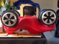
 Electric bobby car build final.jpg 1,488 × 1,600; 404 KB
 Electric bobby car build final usage1.jpg 1,723 × 1,600; 309 KB
 Electric bobby car build flash firmware arch1.png 1,824 × 1,534; 254 KB
 Electric bobby car build flash port1.jpg 2,000 × 1,500; 1.25 MB
 Electric bobby car build flash port2.jpg 2,000 × 1,500; 1.28 MB
 Electric bobby car build motor hall wiring1.jpg 2,000 × 1,500; 1.27 MB
 Electric bobby car build motor wiring1.jpg 2,000 × 1,500; 1.3 MB
 Electric bobby car build motor wiring2.jpg 2,000 × 1,500; 1.06 MB
 Electric bobby car build power buttons1.jpg 2,000 × 1,500; 945 KB
 Electric bobby car build power buttons2.jpg 2,000 × 1,500; 1.08 MB
 Electric bobby car build power buttons3.jpg 2,000 × 1,500; 1.2 MB
 Electric bobby car build power charging1.jpg 2,000 × 1,500; 1.71 MB
 Electric bobby car build power charging2.jpg 2,000 × 1,500; 1,018 KB
 Electric bobby car build steering cad overview1.png 988 × 824; 152 KB
 Electric bobby car build steering rod1.jpg 2,000 × 1,500; 1.19 MB
 Electric bobby car build steering rod2.jpg 2,000 × 1,500; 912 KB
 Electric bobby car build steering rod mounting1.jpg 2,000 × 1,553; 1.19 MB
 Electric bobby car build steering rod mounting2.jpg 2,000 × 1,500; 921 KB
 Electric bobby car build steering rod mounting3.jpg 2,000 × 1,500; 1.5 MB
 Electric bobby car build steering rod support bottom1.jpg 2,000 × 1,500; 410 KB
 Electric bobby car build steering rod support bottom2.jpg 2,000 × 1,500; 849 KB
 Electric bobby car build steering rod support top1.jpg 2,000 × 1,500; 383 KB
 Electric bobby car build steering rod support top2.jpg 2,000 × 1,500; 1.08 MB
 Electric bobby car build steering rod tube1.jpg 2,000 × 1,500; 517 KB
 Electric bobby car build steering rod tube2.jpg 2,000 × 1,500; 776 KB
 Electric bobby car build steering steering wiring1.jpg 2,000 × 1,500; 734 KB
 Electric bobby car build steering steering wiring2.jpg 2,000 × 1,500; 796 KB
 Electric bobby car build steering steering wiring3.jpg 2,000 × 1,500; 923 KB
 Electric bobby car build steering throttle brake mounting1.jpg 2,000 × 1,500; 748 KB
 Electric bobby car build steering throttle brake mounting2.jpg 2,000 × 1,500; 732 KB
 Electric bobby car build steering throttle brake wiring1.jpg 2,000 × 1,500; 1.01 MB
 Electric bobby car build steering throttle brake wiring2.jpg 2,000 × 1,500; 1.15 MB
 Electric bobby car build vibration1.jpg 2,000 × 1,500; 1.32 MB
 Electric bobby car build wheels front assembly1.jpg 2,000 × 1,500; 1.02 MB
 Electric bobby car build wheels front assembly2.jpg 2,000 × 1,500; 1.17 MB
 Electric bobby car build wheels front assembly3.jpg 2,000 × 1,500; 1.15 MB
 Electric bobby car build wheels front assembly4.jpg 2,000 × 1,500; 1.32 MB
 Electric bobby car build wheels front bracket1.jpg 2,000 × 1,500; 1.02 MB
 Electric bobby car build wheels front bracket2.jpg 2,000 × 1,500; 812 KB
 Electric bobby car build wheels front bracket3.jpg 2,000 × 1,500; 441 KB
 Electric bobby car build wheels front bracket4.jpg 2,000 × 1,500; 992 KB
 Electric bobby car build wheels front cad overview1.png 988 × 824; 199 KB
 Electric bobby car build wheels front cad overview2.png 988 × 824; 186 KB
 Electric bobby car build wheels front wiring1.jpg 2,000 × 1,500; 960 KB
 Electric bobby car build wheels front wiring2.jpg 2,000 × 1,500; 911 KB
 Electric bobby car build wheels rear cad overview.png 988 × 824; 142 KB
 Electric bobby car build wheels rear cover1.jpg 2,000 × 1,500; 1.01 MB
 Electric bobby car build wheels rear installing plate1.jpg 2,000 × 1,500; 1.16 MB
 Electric bobby car build wheels rear installing plate2.jpg 2,000 × 1,500; 905 KB
 Electric bobby car build wheels rear mounting1.jpg 2,000 × 1,500; 1.2 MB
 Electric bobby car build wheels rear mounting2.jpg 2,000 × 1,500; 1.23 MB
 Electric bobby car build wheels rear mounting3.jpg 2,000 × 1,500; 1,015 KB
 Electric bobby car build wheels rear plate design.png 988 × 824; 163 KB
 Electric bobby car build wheels rear plate holes1.jpg 2,000 × 1,500; 951 KB
 Electric bobby car build wheels rear plate holes2.jpg 2,000 × 1,500; 1.22 MB
 Electric bobby car build wheels rear plate holes3.jpg 2,000 × 1,500; 1.23 MB
 Electric bobby car build wheels rear plate length1.jpg 2,000 × 1,500; 1.3 MB
 Electric bobby car build wheels rear plate length2.jpg 2,000 × 1,500; 1.02 MB
 Electric bobby car build wheels rear plate screw holes1.jpg 2,000 × 1,500; 1.1 MB
 Electric bobby car build wheels rear plate screw holes2.jpg 2,000 × 1,500; 945 KB
 Electric bobby car build wheels rear plate slots1.jpg 2,000 × 1,500; 871 KB
 Electric bobby car build wheels rear plate slots2.jpg 2,000 × 1,500; 1.39 MB
 Electric bobby car build wheels rear plate slots3.jpg 2,000 × 1,500; 991 KB
 Electric bobby car build wheels rear wiring1.jpg 2,000 × 1,500; 962 KB
 Electric bobby car build wheels rear wiring2.jpg 2,000 × 1,500; 933 KB
 Esky017-1.jpg 650 × 487; 138 KB
 Esky017-2.jpg 650 × 487; 190 KB
 Esky017-7.jpg 650 × 447; 201 KB
 Eye2830bk front.jpg 600 × 211; 33 KB
 Eye2830bk open.jpg 500 × 485; 46 KB
 Eye4860bk front.jpg 600 × 299; 40 KB
 Eye4860bk open.jpg 600 × 577; 73 KB
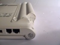
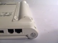
 EzUHF boxes.jpg 1,200 × 794; 151 KB
 EzUHF transmitter board.jpg 1,200 × 794; 235 KB
 Ezuhf spectrum analyzer.png 861 × 540; 87 KB
 Ezuhf spectrum norway.png 394 × 494; 55 KB
 Fcpx export color bland unsaturated.png 1,364 × 539; 639 KB
 Flashlight lithium batteries.jpg 799 × 425; 56 KB
 Floater Jet ar6110b receiver.jpg 680 × 436; 69 KB
 Floater Jet cog.png 684 × 292; 55 KB
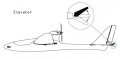 Floater Jet elevator.png 668 × 327; 60 KB
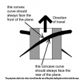 Floater Jet propeller blade.jpg 567 × 567; 34 KB
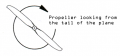 Floater Jet propeller rotation.png 493 × 229; 26 KB
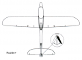 Floater Jet rudder.png 636 × 459; 63 KB
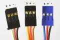 Floater Jet servo connectors.jpg 600 × 399; 53 KB
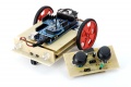 Fpga vehicle overview.jpg 960 × 637; 150 KB
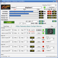 Frsky config.png 670 × 671; 67 KB
 Frsky usb cable.jpg 498 × 318; 30 KB
 Gentoo Desktop.png 640 × 480; 80 KB
 Gentoo Loading.jpg 607 × 454; 94 KB
 GoPro3 reference card.png 1,265 × 1,841; 232 KB
 GoPro reference card.png 621 × 640; 98 KB
 Gps gt01 manual.doc ; 6.38 MB
- Gps gt09 manual.docx ; 15 KB
 Gps holux data cable.png 400 × 210; 33 KB
 Gps holux gpslim 240 unit.png 451 × 190; 31 KB
 Gps holux m-1200 unit.png 453 × 214; 33 KB
 Gps holux operation.png 420 × 210; 17 KB
 Gps st-901 manual.pdf ; 551 KB
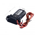
 Gps tracker back.jpg 1,000 × 1,000; 146 KB
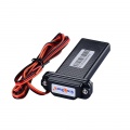
 Gps tracker front.jpg 1,000 × 1,000; 133 KB
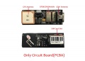 Gps tracker inside.jpg 840 × 600; 121 KB
 Greenscreen after effects autotrace.png 453 × 352; 13 KB
 Greenscreen after effects duplicate layers.png 706 × 194; 32 KB
 Greenscreen after effects duplicate simplechoker fastblur.png 340 × 523; 44 KB
 Greenscreen after effects dvmattepro base matte.png 796 × 406; 85 KB
 Greenscreen after effects dvmattepro color.png 595 × 408; 118 KB
 Greenscreen after effects dvmattepro repick color.png 797 × 407; 95 KB
 Greenscreen after effects finished.png 976 × 556; 709 KB
 Greenscreen after effects matte simplechoker.png 753 × 408; 79 KB
 Greenscreen after effects timeline.png 681 × 628; 200 KB
 Greenscreen after effects trackmatte.png 671 × 202; 24 KB
 Greenscreen subsampling keying.png 720 × 576; 417 KB
 Greenscreen subsampling keying dvmatte.png 390 × 576; 114 KB
 HD DVD Update Folder.PNG 539 × 317; 22 KB
 HD DVD Update MD5.PNG 669 × 170; 6 KB
 HP ProLiant Flash Tool.png 1,024 × 768; 60 KB
 HP ProLiant Smart Array P400.png 518 × 502; 31 KB
 HP ProLiant Smart Update Firmware.png 1,024 × 768; 29 KB
 HP ProLiant iLO2 Firmware.png 1,019 × 689; 107 KB
 HP ProLiant iLO2 Java Settings.png 523 × 546; 36 KB
 Helicopter 3dmode pitch.png 240 × 247; 19 KB
 Helicopter 3dmode throttle.png 240 × 247; 17 KB
 Helicopter 6025-1 60mah charge 0.1a bc6.png 756 × 633; 9 KB
 Helicopter 6025-1 60mah discharge 0.5a bc6.png 756 × 633; 9 KB
 Helicopter 6025-1 60mah discharging 1.0a bc6.png 756 × 633; 9 KB
 Helicopter 6025-1 70mah charge 0.1a bc6.png 756 × 633; 10 KB
 Helicopter 6025-1 70mah discharge 0.5a bc6 59mah.png 756 × 633; 10 KB
 Helicopter 6025-1 70mah discharge 1.0a bc6 50mah.png 756 × 633; 9 KB
 Helicopter 6025-1 70mah discharge precharge 0.1a bc6.png 756 × 633; 9 KB
 Helicopter 6025-1 case.jpg 588 × 600; 86 KB
 Helicopter 6025-1 hand.jpg 600 × 600; 40 KB
 Helicopter 6025-1 inside.jpg 630 × 485; 98 KB
 Helicopter 6025-1 insideleft.jpg 630 × 340; 59 KB
 Helicopter 6025-1 red.jpg 550 × 400; 51 KB
 Helicopter 6025-1 yellow leftside.jpg 600 × 350; 47 KB
 Helicopter Sanhuan 6025 manual.jpg 1,100 × 594; 219 KB
 Helicopter Sanhuan manual.jpg 830 × 500; 148 KB
 Helicopter bantam bc6.jpg 1,100 × 743; 204 KB
 Helicopter bantam bc6 setup.jpg 1,100 × 736; 342 KB
 Helicopter charge connect 3s1 in series.png 1,986 × 1,595; 97 KB
 Helicopter control configurations.png 900 × 648; 114 KB
 Helicopter flightmode switch.jpg 1,044 × 636; 254 KB
 Helicopter gp750.jpg 1,740 × 1,164; 572 KB
 Helicopter gp750 settings.jpg 453 × 173; 24 KB
 Helicopter gyro gain.jpg 800 × 137; 15 KB
 Helicopter head1.jpg 909 × 1,027; 177 KB
 Helicopter head2.jpg 909 × 1,027; 195 KB
 Helicopter logview graph.png 955 × 848; 45 KB
 Helicopter normalmode pitch.png 240 × 247; 19 KB
 Helicopter normalmode throttle.png 240 × 247; 19 KB
 Helicopter rce-bl15x.jpg 1,100 × 298; 80 KB
 Helicopter tail control arm middle.jpg 1,100 × 736; 150 KB
 Helicopter tail setup.png 656 × 461; 90 KB
 Helicopter tailservo perpendicular.jpg 1,100 × 736; 171 KB
 Helicopter throttle trex250 normal.png 240 × 200; 25 KB
 Helicopter throttle trex250 stunt1.png 240 × 200; 23 KB
 Helicopter throttle trex250 stunt2.png 240 × 200; 20 KB
 Helicopter throttlehold switch.jpg 1,044 × 636; 236 KB
 Helicopter thunderpower 860mah.jpg 1,100 × 550; 104 KB
 Helicopter thunderpower 910mah.jpg 1,100 × 550; 101 KB
 Helicopter trex250 backl.jpg 1,100 × 736; 165 KB
 Helicopter trex250 battery.jpg 1,100 × 737; 175 KB
 Helicopter trex250 bottom.jpg 1,100 × 736; 194 KB
 Helicopter trex250 cover backl.jpg 1,100 × 736; 141 KB
 Helicopter trex250 cover frontl.jpg 1,100 × 736; 146 KB
 Helicopter trex250 coverl.jpg 1,100 × 732; 150 KB
 Helicopter trex250 coverr.jpg 1,100 × 736; 162 KB
 Helicopter trex250 esc.jpg 1,100 × 736; 170 KB
 Helicopter trex250 esc room.jpg 1,100 × 736; 191 KB
 Helicopter trex250 front.jpg 1,100 × 737; 161 KB
 Helicopter trex250 frontl.jpg 1,100 × 736; 160 KB
 Helicopter trex250 frontr.jpg 1,100 × 736; 173 KB
 Helicopter trex250 head cover.jpg 1,100 × 736; 103 KB
 Helicopter trex250 head nocover.jpg 1,100 × 730; 127 KB
 Helicopter trex250 head servos.jpg 1,100 × 736; 151 KB
 Helicopter trex250 head servos back.jpg 1,100 × 736; 156 KB
 Helicopter trex250 sidel.jpg 1,100 × 737; 163 KB
 Helicopter trex250 sider.jpg 1,100 × 736; 175 KB
 Helicopter trex250 tail blades.jpg 1,100 × 736; 98 KB
 Helicopter trex250 tail servo.jpg 1,100 × 736; 152 KB
 Helicopter trex250 tail servo gyro.jpg 1,100 × 736; 174 KB
 Helicopter trex250 tail shaft.jpg 1,100 × 736; 101 KB
 Helicopter trex250 top.jpg 736 × 1,100; 106 KB
 Helicopter trex250 transmitter.jpg 1,100 × 736; 177 KB
 Hitachi-LG 79 clean pads.JPG 640 × 480; 182 KB
 Hitachi-LG 79 installed.JPG 640 × 480; 186 KB
 Hitachi-LG 79 overview.JPG 640 × 480; 190 KB
 Hitachi-LG 79 power and ground.JPG 640 × 480; 175 KB
 Hitachi-LG 79 remove resin.JPG 640 × 480; 182 KB
 Hitachi-LG 79 solder pads.JPG 640 × 480; 187 KB
 Hitachi-LG 79 top.JPG 566 × 229; 85 KB
 Hoverboard balance board pcb.jpg 2,400 × 1,588; 872 KB
 Hoverboard battery charger.jpg 1,200 × 900; 463 KB
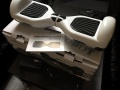
 Hoverboard battery pack.jpg 1,200 × 900; 345 KB
 Hoverboard battery pack spec1.jpg 539 × 400; 93 KB
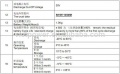 Hoverboard battery pack spec2.jpg 542 × 336; 64 KB
 Hoverboard content.jpg 900 × 675; 196 KB
 Hoverboard front light board.jpg 1,200 × 794; 119 KB
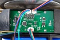
 Hoverboard left main aux circuit boards.jpg 1,200 × 794; 267 KB
 Hoverboard left main aux circuit boards no cables.jpg 1,200 × 794; 258 KB
 Hoverboard left pedal opto interrupter.jpg 1,200 × 794; 116 KB
 Hoverboard left pedal rubber stub motor mount.jpg 1,200 × 794; 259 KB
 Hoverboard left platform.jpg 1,200 × 794; 275 KB
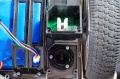
 Hoverboard left power button charging port inside.jpg 1,200 × 794; 104 KB
 Hoverboard left side circuit board1.jpg 1,200 × 794; 288 KB
 Hoverboard left side circuit board2.jpg 1,200 × 794; 282 KB
 Hoverboard left side circuit board3.jpg 1,200 × 794; 322 KB
 Hoverboard left side circuit board4.jpg 1,200 × 794; 445 KB
 Hoverboard left side circuit board5.jpg 1,200 × 794; 458 KB
 Hoverboard left side circuit board6.jpg 1,200 × 794; 449 KB
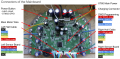
 Hoverboard main board pcb.jpg 2,400 × 1,589; 1.2 MB
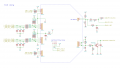 Hoverboard main schematic.png 1,442 × 822; 124 KB
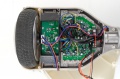
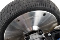 Hoverboard motor.jpg 1,200 × 794; 216 KB
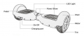
 Hoverboard operation.jpg 790 × 515; 56 KB
 Hoverboard opto sensor fix.jpg 1,200 × 794; 310 KB
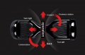
 Hoverboard overview diagram.png 646 × 275; 87 KB
 Hoverboard pinouts STM32F103.png 2,048 × 1,024; 779 KB
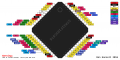
 Hoverboard pinouts main board.png 2,309 × 1,140; 2.43 MB
 Hoverboard right aux circuit board.jpg 1,200 × 794; 300 KB
 Hoverboard right battery aux circuit board.jpg 1,200 × 794; 221 KB


