Uncategorized files
From ivc wiki
Jump to navigationJump to search
Showing below up to 250 results in range #301 to #550.
View (previous 250 | next 250) (20 | 50 | 100 | 250 | 500)
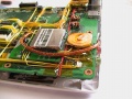
 Eee flashdrive controller.jpg 640 × 480; 177 KB
 Eee flashdrive devicemanager.png 496 × 248; 16 KB
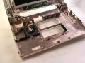
 Eee flashdrive height.jpg 640 × 480; 165 KB
 Eee flashdrive mounted.jpg 640 × 480; 183 KB
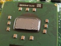
 Eee flashdrive nand.jpg 640 × 480; 170 KB
 Eee flashdrive newloc mounted.jpg 640 × 480; 186 KB
 Eee flashdrive newloc mounted side.jpg 640 × 480; 180 KB
 Eee flashdrive open back.jpg 640 × 480; 94 KB
 Eee flashdrive open front.jpg 640 × 480; 93 KB
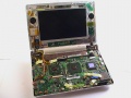
 Eee flashdrive overview.jpg 640 × 480; 187 KB
 Eee fmtransmitter adapter.jpg 640 × 480; 156 KB
 Eee fmtransmitter antenna mounted.jpg 640 × 480; 179 KB
 Eee fmtransmitter antenna ready.jpg 640 × 480; 170 KB
 Eee fmtransmitter antenna side.jpg 640 × 480; 158 KB
 Eee fmtransmitter audio motherboard.jpg 640 × 480; 175 KB
 Eee fmtransmitter back.jpg 640 × 480; 167 KB
 Eee fmtransmitter box.jpg 640 × 480; 173 KB
 Eee fmtransmitter buttons.jpg 640 × 480; 178 KB
 Eee fmtransmitter coaxcable.jpg 480 × 640; 81 KB
 Eee fmtransmitter front.jpg 640 × 480; 180 KB
 Eee fmtransmitter height.jpg 640 × 480; 188 KB
 Eee fmtransmitter open.jpg 640 × 480; 156 KB
 Eee fmtransmitter side.jpg 640 × 480; 178 KB
 Eee fmtransmitter stripped.jpg 640 × 480; 109 KB
 Eee fmtransmitter top.jpg 640 × 480; 172 KB
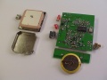
 Eee gps antenna crystal.jpg 640 × 480; 94 KB
 Eee gps antenna mounted.jpg 640 × 480; 162 KB
 Eee gps antenna mounted side.jpg 640 × 480; 171 KB
 Eee gps antenna soldered.jpg 640 × 480; 190 KB
 Eee gps cable insulation.jpg 640 × 480; 179 KB
 Eee gps cable joint.jpg 640 × 480; 147 KB
 Eee gps chassis fit.jpg 640 × 480; 168 KB
 Eee gps chassis space.jpg 640 × 480; 181 KB
 Eee gps devicemanager.png 496 × 248; 16 KB
 Eee gps display after.jpg 640 × 480; 182 KB
 Eee gps display before.jpg 640 × 480; 182 KB
 Eee gps height.jpg 640 × 480; 161 KB
 Eee gps kit.jpg 640 × 480; 107 KB
 Eee gps mounted.jpg 640 × 480; 174 KB
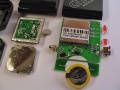
 Eee gps overview.jpg 640 × 480; 149 KB
 Eee gps stripped back.jpg 640 × 480; 100 KB
 Eee gps stripped front.jpg 640 × 480; 137 KB
 Eee hdtune adatasdhccard 8gb.png 570 × 464; 39 KB
 Eee hdtune adatasdhccard 8gb 900mhz.png 570 × 464; 39 KB
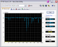
 Eee hdtune siliconmotion 4gb.png 570 × 464; 41 KB
 Eee hdtune siliconmotion 4gb 900mhz.png 570 × 464; 41 KB
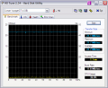
 Eee hdtune voyagergt 4gb.png 570 × 464; 39 KB
 Eee hdtune voyagergt 4gb 900mhz.png 570 × 464; 39 KB
 Eee heatsink artic silver.jpg 640 × 480; 93 KB
 Eee heatsink chips clean.jpg 640 × 480; 176 KB
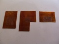
 Eee heatsink copper plates.jpg 640 × 480; 154 KB
 Eee heatsink copper plates aligned.jpg 640 × 480; 185 KB
 Eee heatsink copper plates kapton.jpg 640 × 480; 154 KB
 Eee heatsink dimensions.gif 443 × 215; 3 KB
 Eee heatsink keyboard shielding.jpg 640 × 480; 78 KB
 Eee heatsink lid keyboard.jpg 640 × 480; 65 KB
 Eee heatsink location animation.gif 400 × 280; 118 KB
 Eee heatsink old thermal pads.jpg 640 × 480; 174 KB
 Eee heatsink old thermal pads moved.jpg 640 × 480; 165 KB
 Eee heatsink thermal compound overview.jpg 640 × 480; 179 KB
 Eee heatsink thermal compound processor.jpg 640 × 480; 163 KB
 Eee heatsink top casing assembled.jpg 640 × 480; 164 KB
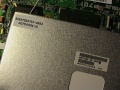 Eee lcd modelnumber.jpg 640 × 480; 170 KB
 Eee linux ubuntu cover.jpg 900 × 640; 126 KB
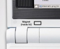 Eee magnet lid.jpg 430 × 350; 37 KB
 Eee magnet sensor.jpg 430 × 350; 47 KB
 Eee memory 910gml.png 556 × 112; 13 KB
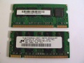 Eee memory modules back.jpg 640 × 480; 141 KB
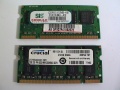 Eee memory modules front.jpg 640 × 480; 142 KB
 Eee mini pcie removed.jpg 285 × 507; 86 KB
 Eee modem connector.jpg 640 × 480; 99 KB
 Eee modem devicemanager.png 496 × 248; 16 KB
 Eee modem driverfolder.png 448 × 281; 31 KB
 Eee modem driverinf.png 472 × 266; 15 KB
 Eee modem height.jpg 640 × 480; 149 KB
 Eee modem mounted.jpg 640 × 480; 179 KB
 Eee modem signals header.jpg 640 × 480; 173 KB
 Eee modem signals mdc.jpg 640 × 480; 168 KB
 Eee modem wires.jpg 640 × 480; 183 KB
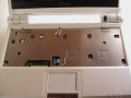
 Eee open bottom.jpg 640 × 480; 122 KB
 Eee open display.jpg 640 × 480; 90 KB
 Eee open front.jpg 640 × 480; 131 KB
 Eee overclock 3dmark.png 516 × 345; 48 KB
 Eee overclock cpuz.png 390 × 442; 25 KB
 Eee overclock cpuz 1101mhz.png 390 × 441; 25 KB
 Eee overclock cpuz 1101mhz mainboard.png 390 × 442; 18 KB
 Eee overclock cpuz 1101mhz memory.png 390 × 442; 19 KB
 Eee overclock cpuz 1101mhz spd.png 390 × 442; 21 KB
 Eee overclock memset pc4200.png 287 × 577; 18 KB
 Eee overclock setfsb.png 518 × 264; 20 KB
 Eee overclock setfsb 1101mhz.png 518 × 264; 20 KB
 Eee overclock superpi.png 512 × 305; 14 KB
 Eee overview complete.jpg 640 × 480; 108 KB
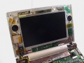 Eee overview display.jpg 640 × 480; 168 KB
 Eee overview march08 display.jpg 640 × 480; 107 KB
 Eee overview march08 motherboard bottom.jpg 640 × 480; 185 KB
 Eee overview march08 motherboard bottom closeup1.jpg 640 × 480; 176 KB
 Eee overview march08 motherboard bottom closeup2.jpg 640 × 480; 185 KB
 Eee overview march08 motherboard bottom closeup3.jpg 640 × 480; 188 KB
 Eee overview motherboard bottom.jpg 640 × 480; 164 KB
 Eee overview motherboard bottom1.jpg 640 × 480; 184 KB
 Eee overview motherboard bottom2.jpg 640 × 480; 189 KB
 Eee overview motherboard bottom3.jpg 640 × 480; 169 KB
 Eee overview motherboard top.jpg 640 × 480; 182 KB
 Eee power signal diagram bottom.jpg 1,579 × 1,100; 549 KB
 Eee power signal diagram top.jpg 1,596 × 1,100; 537 KB
 Eee powerswitch 10dip assembled.jpg 640 × 480; 103 KB
 Eee powerswitch 10dip mounted.jpg 640 × 480; 184 KB
 Eee powerswitch 10dip mounted front.jpg 640 × 480; 185 KB
 Eee powerswitch 10dip old new.jpg 640 × 480; 183 KB
 Eee powerswitch 5v point1.jpg 640 × 480; 173 KB
 Eee powerswitch 5v point2.jpg 640 × 480; 180 KB
 Eee powerswitch 5v point3.jpg 640 × 480; 173 KB
 Eee powerswitch bay.jpg 640 × 480; 189 KB
 Eee powerswitch parts.jpg 640 × 480; 88 KB
 Eee setfsb.png 518 × 264; 24 KB
 Eee sound recorder.png 327 × 286; 18 KB
 Eee ssd intel.jpg 747 × 518; 164 KB
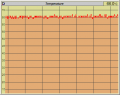
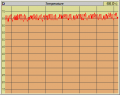
 Eee temper.jpg 547 × 503; 101 KB
 Eee temperature copper plates sample 1 mobmeter.png 423 × 336; 7 KB
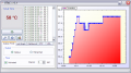
 Eee temperature copper plates sample 1 utac.png 725 × 405; 46 KB
 Eee temperature copper plates sample 2 mobmeter.png 423 × 336; 6 KB
 Eee temperature copper plates sample 2 utac.png 725 × 405; 45 KB
 Eee temperature copper plates sample 3 mobmeter.png 423 × 336; 6 KB
 Eee temperature copper plates sample 3 utac.png 725 × 405; 45 KB
 Eee temperature sensor bottom.jpg 640 × 480; 107 KB
 Eee temperature sensor box.jpg 640 × 480; 102 KB
 Eee temperature sensor mounted.jpg 640 × 480; 180 KB
 Eee temperature sensor mounted overview.jpg 640 × 480; 176 KB
 Eee temperature sensor top.jpg 640 × 480; 101 KB
 Eee temperature superpi.png 512 × 196; 12 KB
 Eee temperature thermal pads sample 1 mobmeter.png 423 × 336; 6 KB
 Eee temperature thermal pads sample 1 utac.png 725 × 405; 45 KB
 Eee temperature thermal pads sample 2 mobmeter.png 423 × 336; 7 KB
 Eee temperature thermal pads sample 2 utac.png 725 × 405; 43 KB
 Eee temperature thermal pads sample 3 mobmeter.png 423 × 336; 6 KB
 Eee temperature thermal pads sample 3 utac.png 725 × 405; 38 KB
 Eee touch screen overlay.png 496 × 229; 11 KB
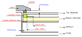
 Eee touch screen resistive.gif 469 × 151; 15 KB
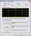 Eee touchkit.png 401 × 459; 18 KB
 Eee touchkit calibration.jpg 900 × 602; 116 KB
 Eee touchscreen antiglare brightness bottom.jpg 640 × 480; 185 KB
 Eee touchscreen antiglare brightness side.jpg 640 × 480; 174 KB
 Eee touchscreen antiglare brightness windows.jpg 640 × 480; 174 KB
 Eee touchscreen antiglare brightness windows closeup.jpg 640 × 480; 179 KB
 Eee touchscreen antiglare cleanup.jpg 640 × 480; 167 KB
 Eee touchscreen antiglare corner removed.jpg 640 × 480; 190 KB
 Eee touchscreen antiglare inplace.jpg 640 × 480; 178 KB
 Eee touchscreen antiglare lcd module.jpg 640 × 480; 143 KB
 Eee touchscreen antiglare lift corner.jpg 640 × 480; 166 KB
 Eee touchscreen antiglare paper towel.jpg 640 × 480; 182 KB
 Eee touchscreen antiglare paper towel saturated.jpg 640 × 480; 178 KB
 Eee touchscreen antiglare paper towel saturated side.jpg 640 × 480; 182 KB
 Eee touchscreen antiglare removal finished.jpg 640 × 480; 161 KB
 Eee touchscreen antiglare removed.jpg 640 × 480; 186 KB
 Eee touchscreen antiglare removed entirely.jpg 640 × 480; 187 KB
 Eee touchscreen controller back.jpg 640 × 480; 107 KB
 Eee touchscreen controller ends cut.jpg 640 × 480; 116 KB
 Eee touchscreen controller front.jpg 640 × 480; 125 KB
 Eee touchscreen controller mounted.jpg 640 × 480; 181 KB
 Eee touchscreen controller overlay wires.jpg 640 × 480; 177 KB
 Eee touchscreen controller overlay wires right.jpg 640 × 480; 190 KB
 Eee touchscreen controller wires middle.jpg 640 × 480; 181 KB
 Eee touchscreen front panel bottom.jpg 640 × 480; 146 KB
 Eee touchscreen front panel hook removed.jpg 640 × 480; 91 KB
 Eee touchscreen front panel overview.jpg 640 × 480; 159 KB
 Eee touchscreen front panel right.jpg 640 × 480; 154 KB
 Eee touchscreen front panel top.jpg 640 × 480; 73 KB
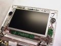
 Eee touchscreen installed.jpg 640 × 480; 164 KB
 Eee touchscreen installed height.jpg 640 × 480; 173 KB
 Eee touchscreen monitor blanket.jpg 640 × 480; 179 KB
 Eee touchscreen monitor ground gasket.jpg 640 × 480; 104 KB
 Eee touchscreen monitor mount area.jpg 640 × 480; 110 KB
 Eee touchscreen monitor unit.jpg 640 × 480; 179 KB
 Eee touchscreen overlay align bottom-right.jpg 640 × 480; 179 KB
 Eee touchscreen overlay align top-left.jpg 640 × 480; 146 KB
 Eee touchscreen overlay pads.jpg 640 × 480; 188 KB
 Eee touchscreen overlay pads height.jpg 640 × 480; 74 KB
 Eee touchscreen overlay wires soldered.jpg 640 × 480; 115 KB
 Eee touchscreen remove frame.jpg 640 × 480; 86 KB
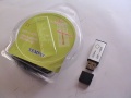
 Eee usbhub box.jpg 640 × 480; 90 KB
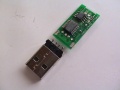
 Eee usbhub chip.jpg 393 × 397; 78 KB
 Eee usbhub devicemanager.png 496 × 248; 16 KB
 Eee usbhub first.jpg 640 × 480; 177 KB
 Eee usbhub first bottom.jpg 640 × 480; 104 KB
 Eee usbhub first top.jpg 640 × 480; 128 KB
 Eee usbhub height.jpg 640 × 480; 95 KB
 Eee usbhub open.jpg 640 × 480; 100 KB
 Eee usbhub port closeup.jpg 640 × 480; 178 KB
 Eee usbhub port overview.jpg 640 × 480; 176 KB
 Eee usbhub powerproperties1.png 413 × 455; 21 KB
 Eee usbhub powerproperties2.png 413 × 455; 21 KB
 Eee usbhub second.jpg 640 × 480; 177 KB
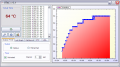
 Eee utac.jpg 725 × 405; 125 KB
 Eee wifi antenna mounted.jpg 640 × 480; 181 KB
 Eee wifi antenna side.jpg 640 × 480; 96 KB
 Eee wifi antenna sideways.jpg 640 × 480; 177 KB
 Eee wifi antenna stripped.jpg 640 × 480; 97 KB
 Eee wifi connector.jpg 640 × 480; 123 KB
 Eee wifi connectors.jpg 640 × 480; 182 KB
 Eee wifi devicemanager.png 496 × 248; 16 KB
 Eee wifi intel front.jpg 640 × 480; 110 KB
 Eee wifi intel inside.jpg 640 × 480; 108 KB
 Eee wifi mounted.jpg 640 × 480; 186 KB
 Eee wifi transfer g-network.png 607 × 520; 59 KB
 Eee wifi wii antenna.jpg 640 × 480; 100 KB
 Electric bobby car build base cut heatgun.jpg 2,000 × 1,500; 698 KB
 Electric bobby car build base cut internal bay1.jpg 2,000 × 1,500; 678 KB
 Electric bobby car build base cut internal bay2.jpg 2,000 × 1,500; 1.04 MB
 Electric bobby car build base cut internal bay3.jpg 2,000 × 1,500; 1.02 MB
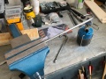
 Electric bobby car build base cut rear slot1.jpg 2,000 × 1,500; 916 KB
 Electric bobby car build base cut rear slot2.jpg 2,000 × 1,500; 697 KB
 Electric bobby car build base cut rear slot3.jpg 2,000 × 1,500; 1.06 MB
 Electric bobby car build base cut rear slot4.jpg 2,000 × 1,500; 835 KB
 Electric bobby car build base rear mounting structure1.jpg 2,000 × 1,500; 1.05 MB
 Electric bobby car build base rear mounting structure2.jpg 2,000 × 1,500; 923 KB
 Electric bobby car build base rear structure1.jpg 2,000 × 1,500; 1,004 KB
 Electric bobby car build base rear structure2.jpg 2,000 × 1,500; 1.04 MB
 Electric bobby car build base rear structure3.jpg 2,000 × 1,500; 996 KB
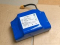 Electric bobby car build battery1.jpg 2,000 × 1,500; 813 KB
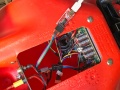
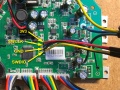
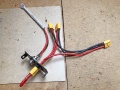
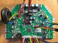 Electric bobby car build controller1.jpg 2,000 × 1,500; 1.47 MB
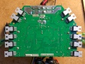 Electric bobby car build controller2.jpg 2,000 × 1,500; 1.12 MB
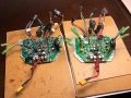 Electric bobby car build controller3.jpg 2,000 × 1,500; 1.51 MB
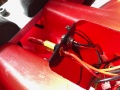
 Electric bobby car build controller mounting1.jpg 2,000 × 1,500; 1.22 MB
 Electric bobby car build controller mounting2.jpg 2,000 × 1,500; 1.22 MB
 Electric bobby car build controller mounting3.jpg 2,000 × 1,500; 1.31 MB
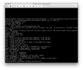
 Electric bobby car build debug console arch1.png 2,260 × 1,820; 367 KB
 Electric bobby car build debugging port1.jpg 2,000 × 1,500; 1.2 MB
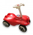 Electric bobby car build final.jpg 1,488 × 1,600; 404 KB
 Electric bobby car build final usage1.jpg 1,723 × 1,600; 309 KB
 Electric bobby car build flash firmware arch1.png 1,824 × 1,534; 254 KB
 Electric bobby car build flash port1.jpg 2,000 × 1,500; 1.25 MB
 Electric bobby car build flash port2.jpg 2,000 × 1,500; 1.28 MB
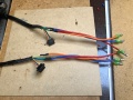
 Electric bobby car build motor hall wiring1.jpg 2,000 × 1,500; 1.27 MB
 Electric bobby car build motor wiring1.jpg 2,000 × 1,500; 1.3 MB
 Electric bobby car build motor wiring2.jpg 2,000 × 1,500; 1.06 MB
 Electric bobby car build power buttons1.jpg 2,000 × 1,500; 945 KB
 Electric bobby car build power buttons2.jpg 2,000 × 1,500; 1.08 MB
 Electric bobby car build power buttons3.jpg 2,000 × 1,500; 1.2 MB
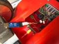
 Electric bobby car build power charging1.jpg 2,000 × 1,500; 1.71 MB
 Electric bobby car build power charging2.jpg 2,000 × 1,500; 1,018 KB
 Electric bobby car build steering cad overview1.png 988 × 824; 152 KB
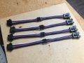
 Electric bobby car build steering rod1.jpg 2,000 × 1,500; 1.19 MB
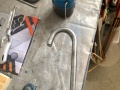 Electric bobby car build steering rod2.jpg 2,000 × 1,500; 912 KB
 Electric bobby car build steering rod mounting1.jpg 2,000 × 1,553; 1.19 MB
 Electric bobby car build steering rod mounting2.jpg 2,000 × 1,500; 921 KB
 Electric bobby car build steering rod mounting3.jpg 2,000 × 1,500; 1.5 MB
 Electric bobby car build steering rod support bottom1.jpg 2,000 × 1,500; 410 KB
 Electric bobby car build steering rod support bottom2.jpg 2,000 × 1,500; 849 KB
 Electric bobby car build steering rod support top1.jpg 2,000 × 1,500; 383 KB


