Difference between revisions of "Raspberry Pi Dummy Camera"
(Created page with "This project uses the Raspberry Pi Camera V2.1 inside a dummy camera dome, making it a real IP camera for low cost with a nice appearance. == BOM == == 3D parts == == Confi...") |
|||
| (21 intermediate revisions by the same user not shown) | |||
| Line 1: | Line 1: | ||
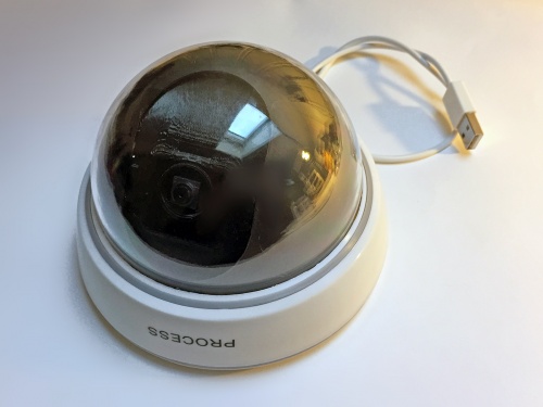
[[Image:Dummy camera complete top.jpg|500px|right]] | |||
== | This project uses the Raspberry Pi V2 8MP camera inside a dummy camera dome to provide a fully fledged 25FPS motion-JPEG IP camera. The IP camera is based on the [https://github.com/ccrisan/motioneyeos MotionEyeOS] for the Raspberry Pi 3. It is powered by a 5V USB wall adapter. | ||
== Parts == | |||
To build this IP camera you need the following parts: | |||
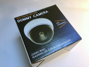
* 1x [http://www.ebay.com/itm/311399189927 Dummy Home Surveillance CCTV Security Dome Camera w/ Flashing Red LED Light] - eBay 5USD | |||
* 1x [https://www.adafruit.com/product/3055 Raspberry Pi 3 - Model B - ARMv8 with 1G RAM] - Adafruit 40USD | |||
* 1x [https://www.adafruit.com/product/3099 Raspberry Pi Camera Board v2 Sony 8MP] - Adafruit 30USD | |||
* 1x [http://www.ebay.com/itm/231648525739 Universal EU 2A AC Micro USB Cable Power Wall Charger Adapter For Mobile Phone] - eBay 3.50USD | |||
* 1x [http://store.ivc.no/ Dummy Camera RPI3 Holder - custom] - ivc 12USD | |||
* 1x [http://store.ivc.no/ Dummy Camera RPI Camera v2 Holder - custom] - ivc 10USD | |||
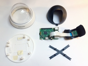
[[Image:Dummy camera overview.jpg|300px]] [[Image:Dummy camera box.jpg|300px]] | |||
== 3D parts == | == 3D parts == | ||
[[Image:Dummy camera cad parts.png|300px]] | |||
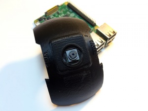
The holder for the Raspberry Pi camera is custom designed to to fit inside the dummy camera dome. It is made to allow adjustment of the view along the vertical axis. | |||
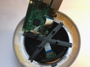
To keep the Raspberry Pi 3 in place, there is a "X" bracket that fits between the existing screw bosses inside the enclosure. | |||
* [http://beta.ivc.no/dummy_cam/dummy_cam_parts.rar Dummy Camera Raspberry Pi parts] - CAD models - STL for print, STEP to modify part | |||
== Build == | |||
Open the dummy camera and disassemble the internal parts. Remove the unused parts like the LED, battery tabs, adhesives, and fake camera lens compartment. | |||
Use a flush cutter to remove all battery cavity, ring around the buzzer grill, excessive extruded plastic tabs, and on/off tabs. Make sure to keep the three screw bosses and support bosses intact. Use good tape to keep the battery compartment cover in place. | |||
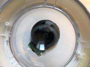
[[Image:Dummy camera dome quality.jpg|300px]] | |||
'''Note:''' The optical quality of the transparent dome plastic is far from the best, the view is a little distorted and not consistent. To get the best possible picture, it is important that the RPI camera is touching the inside of the dome to minimize the distortion through the transparent plastic. | |||
[[Image:Dummy camera raspberry pi camera mount part.jpg|300px]] [[Image:Dummy camera raspberry pi camera installed.jpg|300px]] [[Image:Dummy camera raspberry pi camera inside cover installed.jpg|300px]] | |||
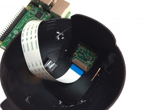
Mount the RPI camera inside the custom camera holder and insert the black internal support inside the dome. Use adhesive tape to secure the custom holder at the desired vertical angle. | |||
[[Image:Dummy camera raspberry pi holder part.jpg|300px]] [[Image:Dummy camera raspberry pi installed.jpg|300px]] [[Image:Dummy camera raspberry pi camera cable close-up.jpg|300px]] | |||
Put on the RPI board holder and mount the RPI at an angle, up-side-down. | |||
[[Image:Dummy camera cable notch.jpg|300px]] [[Image:Dummy camera cable installed.jpg|300px]] [[Image:Dummy camera assemble enclosure.jpg|300px]] | |||
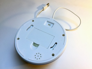
Make a small notch at the rear of the bottom plate and connect the USB power with a knot as strain relief. | |||
[[Image:Dummy camera complete bottom.jpg|300px]] [[Image:Dummy camera complete top.jpg|300px]] | |||
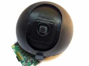
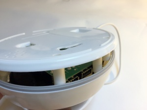
Close up the bottom and top enclosure. Make sure to align the tabs on the top and bottom enclosure to get a good fit. | |||
== Configuration == | == Configuration == | ||
Download and copy the MotionEyeOS image to a SD card using the following Wiki installation guide | |||
* [https://github.com/ccrisan/motioneyeos/wiki/Installation MotionEyeOS Installation] | |||
[[Image:Dummy camera web administration.png|350px]] | |||
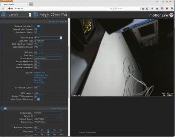
Connect ethernet and find the DHCP ip address for the RPI, or connect HDMI and setup the wifi. Open http://192.168.x.x and use 'admin' as the login to configure MotionEye. The camera should be automatically be detected if it is connected. | |||
'''Change settings:''' | |||
* Services: | |||
** Enable FTP server: off | |||
** Enable Samba server: on | |||
** Samba write support: on | |||
* Expert settings | |||
** GPU Memory: 384MB | |||
** Enable System Monitoring: on - for system temperature, load and bandwidth usage | |||
* Video device | |||
** Frame rate: 30 | |||
** Video Resolution: 1024x768 | |||
** Video rotation: 0 degrees | |||
* Text overlay: on | |||
* Video streaming: | |||
** Streaming Frame Rate: 30 | |||
** Streaming Quality: 75% - for about 1MB/s stream | |||
* Still images: off | |||
* Movies: on | |||
** Movie Quality: 75% | |||
* Motion detection: on | |||
** Frame Change Threshold: 2% | |||
The streaming address for MJPEG will be http://192.168.x.x:8081 and for current still image http://192.168.x.x/picture/1/current/. | |||
== Demonstration == | == Demonstration == | ||
== References == | |||
* [https://darkbluebit.com/raspberry-pi/low-cost-security-camera/ Low-cost Security Camera using a Raspberry Pi] | |||
Latest revision as of 14:23, 16 March 2017
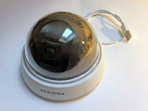
This project uses the Raspberry Pi V2 8MP camera inside a dummy camera dome to provide a fully fledged 25FPS motion-JPEG IP camera. The IP camera is based on the MotionEyeOS for the Raspberry Pi 3. It is powered by a 5V USB wall adapter.
Parts
To build this IP camera you need the following parts:
- 1x Dummy Home Surveillance CCTV Security Dome Camera w/ Flashing Red LED Light - eBay 5USD
- 1x Raspberry Pi 3 - Model B - ARMv8 with 1G RAM - Adafruit 40USD
- 1x Raspberry Pi Camera Board v2 Sony 8MP - Adafruit 30USD
- 1x Universal EU 2A AC Micro USB Cable Power Wall Charger Adapter For Mobile Phone - eBay 3.50USD
- 1x Dummy Camera RPI3 Holder - custom - ivc 12USD
- 1x Dummy Camera RPI Camera v2 Holder - custom - ivc 10USD
3D parts
File:Dummy camera cad parts.png
The holder for the Raspberry Pi camera is custom designed to to fit inside the dummy camera dome. It is made to allow adjustment of the view along the vertical axis.
To keep the Raspberry Pi 3 in place, there is a "X" bracket that fits between the existing screw bosses inside the enclosure.
- Dummy Camera Raspberry Pi parts - CAD models - STL for print, STEP to modify part
Build
Open the dummy camera and disassemble the internal parts. Remove the unused parts like the LED, battery tabs, adhesives, and fake camera lens compartment.
Use a flush cutter to remove all battery cavity, ring around the buzzer grill, excessive extruded plastic tabs, and on/off tabs. Make sure to keep the three screw bosses and support bosses intact. Use good tape to keep the battery compartment cover in place.
Note: The optical quality of the transparent dome plastic is far from the best, the view is a little distorted and not consistent. To get the best possible picture, it is important that the RPI camera is touching the inside of the dome to minimize the distortion through the transparent plastic.
Mount the RPI camera inside the custom camera holder and insert the black internal support inside the dome. Use adhesive tape to secure the custom holder at the desired vertical angle.
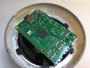
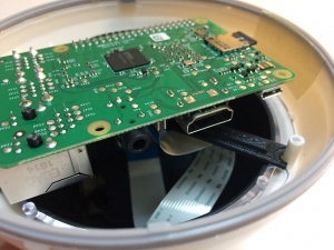
Put on the RPI board holder and mount the RPI at an angle, up-side-down.
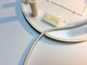
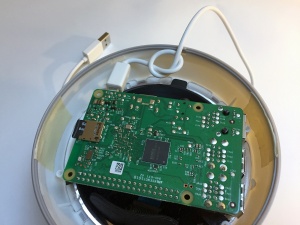
Make a small notch at the rear of the bottom plate and connect the USB power with a knot as strain relief.
Close up the bottom and top enclosure. Make sure to align the tabs on the top and bottom enclosure to get a good fit.
Configuration
Download and copy the MotionEyeOS image to a SD card using the following Wiki installation guide
Connect ethernet and find the DHCP ip address for the RPI, or connect HDMI and setup the wifi. Open http://192.168.x.x and use 'admin' as the login to configure MotionEye. The camera should be automatically be detected if it is connected.
Change settings:
- Services:
- Enable FTP server: off
- Enable Samba server: on
- Samba write support: on
- Expert settings
- GPU Memory: 384MB
- Enable System Monitoring: on - for system temperature, load and bandwidth usage
- Video device
- Frame rate: 30
- Video Resolution: 1024x768
- Video rotation: 0 degrees
- Text overlay: on
- Video streaming:
- Streaming Frame Rate: 30
- Streaming Quality: 75% - for about 1MB/s stream
- Still images: off
- Movies: on
- Movie Quality: 75%
- Motion detection: on
- Frame Change Threshold: 2%
The streaming address for MJPEG will be http://192.168.x.x:8081 and for current still image http://192.168.x.x/picture/1/current/.
