Difference between revisions of "Cloverleaf FPV antenna"
| (10 intermediate revisions by the same user not shown) | |||
| Line 1: | Line 1: | ||
[[Image:cloverleaf_antenna.jpg|right|500px]] | [[Image:cloverleaf_antenna.jpg|right|500px]] | ||
This is a circularly polarized aerial antenna spesially designed for FPV use. Because of the almost ideal 1.2dBi isotropic radiation pattern, it is suitable as a transmitter antenna (transmitting video signal down to ground). | This is a 2.4GHz circularly polarized aerial antenna spesially designed for FPV use. Because of the almost ideal 1.2dBi isotropic radiation pattern, it is suitable as a transmitter antenna (transmitting video signal down to ground). | ||
The three lobes is key to get an uniform radiation pattern. When mounted on an airplane the lobes will generate a little drag but less compared to a four lobe Skew Planar antenna - which makes a good receiver antenna. | |||
== Construction == | == Construction == | ||
The video below shows the design and | The video below shows the design and geometry of the antenna. | ||
<html><object width="420" height="315"><param name="movie" value="http://www.youtube.com/v/submrMo5QWs?version=3&hl=en_US"></param><param name="allowFullScreen" value="true"></param><param name="allowscriptaccess" value="always"></param><embed src="http://www.youtube.com/v/submrMo5QWs?version=3&hl=en_US" type="application/x-shockwave-flash" width="420" height="315" allowscriptaccess="always" allowfullscreen="true"></embed></object></html> | <html><object width="420" height="315"><param name="movie" value="http://www.youtube.com/v/submrMo5QWs?version=3&hl=en_US"></param><param name="allowFullScreen" value="true"></param><param name="allowscriptaccess" value="always"></param><embed src="http://www.youtube.com/v/submrMo5QWs?version=3&hl=en_US" type="application/x-shockwave-flash" width="420" height="315" allowscriptaccess="always" allowfullscreen="true"></embed></object></html> | ||
== Radiation pattern == | == Radiation pattern == | ||
The images below | The images below shows the radiation pattern on the horizontal and vertical axes. | ||
[[Image:cloverleaf_pattern_hor.jpg|350px]] [[Image:cloverleaf_pattern_vert.jpg|350px]] | [[Image:cloverleaf_pattern_hor.jpg|350px]] [[Image:cloverleaf_pattern_vert.jpg|350px]] | ||
== Build == | == Build == | ||
Fortunately the original inventor of the antenna, IBCrazy, has provided an excellent guide on how to construct the antenna. Only a few parts are needed. | [[Image:cloverleaf_sketch.jpg|right|300px]] Fortunately the original inventor of the antenna, IBCrazy, has provided an excellent guide on how to construct the antenna. Only a few parts are needed. | ||
* 0.8 mm MIG welding wire - ask your local car or repair shop | * 0.8 mm MIG welding wire - ask your local car or repair shop | ||
* SMA connector - either RP-SMA or SMA depending on the transmitter output | * SMA connector - either RP-SMA or SMA depending on the transmitter output | ||
* 50 Ohm RG58 coax cable - short piece | * 50 Ohm RG58 or RG316 coax cable - short piece, I use RG316 | ||
* Solder, pliers, knife | * Solder, pliers, knife | ||
The antenna below is right hand circular polarized and should be used with another right hand circular polarized antenna for best performance, | The antenna below is right hand circular polarized and should be used with another right hand circular polarized antenna for best performance, a linear antenna will endure a 3dB loss. I aimed for 2510Mhz when creating my antenna as the frequency provides a lower noise-floor and is used for aerial video in Europe. | ||
Using the formula provided by IBCrazy and my desired way of mounting the lobes to the side of the connector shaft, I ended on the following wire length: | Using the formula provided by IBCrazy and my desired way of mounting the lobes to the side of the connector shaft, I ended on the following wire length: | ||
| Line 42: | Line 44: | ||
The hard part is to solder the short mounting taps on the side of the connector and then aligning all the three other ends on the center conductor. | The hard part is to solder the short mounting taps on the side of the connector and then aligning all the three other ends on the center conductor. | ||
[[Image:cloverleaf_side.jpg| | [[Image:cloverleaf_side.jpg|500px]] [[Image:cloverleaf_top.jpg|500px]] | ||
== References == | == References == | ||
* [http://www.rcgroups.com/forums/showthread.php?t=1388264 Build IBCrazy's Cloverleaf] | * [http://www.rcgroups.com/forums/showthread.php?t=1388264 Build IBCrazy's Cloverleaf] | ||
* [http://rcexplorer.se/page14/CPantennas/CL/CL.html RCExplorer Cloverleaf antenna] | |||
Latest revision as of 16:04, 25 March 2013
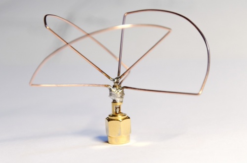
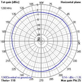
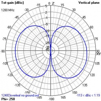
This is a 2.4GHz circularly polarized aerial antenna spesially designed for FPV use. Because of the almost ideal 1.2dBi isotropic radiation pattern, it is suitable as a transmitter antenna (transmitting video signal down to ground).
The three lobes is key to get an uniform radiation pattern. When mounted on an airplane the lobes will generate a little drag but less compared to a four lobe Skew Planar antenna - which makes a good receiver antenna.
Construction
The video below shows the design and geometry of the antenna.
Radiation pattern
The images below shows the radiation pattern on the horizontal and vertical axes.
Build
Fortunately the original inventor of the antenna, IBCrazy, has provided an excellent guide on how to construct the antenna. Only a few parts are needed.
- 0.8 mm MIG welding wire - ask your local car or repair shop
- SMA connector - either RP-SMA or SMA depending on the transmitter output
- 50 Ohm RG58 or RG316 coax cable - short piece, I use RG316
- Solder, pliers, knife
The antenna below is right hand circular polarized and should be used with another right hand circular polarized antenna for best performance, a linear antenna will endure a 3dB loss. I aimed for 2510Mhz when creating my antenna as the frequency provides a lower noise-floor and is used for aerial video in Europe.
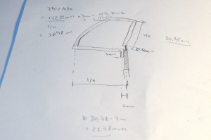
Using the formula provided by IBCrazy and my desired way of mounting the lobes to the side of the connector shaft, I ended on the following wire length:
Wire length in mm = 307022/f in MHz = 307022/2510MHz = 122.32mm for the base wire
Add 3mm for mounting = 122.32mm + 3mm = 125.32mm
Subtract the distance from the coax center to the side = 125.32mm - 2mm = 123.32mm
I cut three pieces of MIG wire and sanded down the ends. Then, began bending one end to ¼th wavelength. Measure from the end to the inside of the bend.
¼th wavelength = 307022/2510MHz/4 = 30.58mm
Next, on the other end of the wire I bent the second bend at the following point after including the short mounting bends (3 mm for mounting, 2 mm from the coax center).
Ground bend = 30.58mm + 3 mm - 2 mm = 31.58mm
Bend the middle section of the U-shaped wire into an arc so that the two ends meet.
Lastly, position the last 31.58mm length on the pliers and adjust the angle to be perfect 45 degrees to the left, when viewing from you. Measure 3 mm in and bend the short mounting taps.
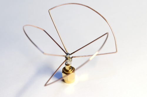
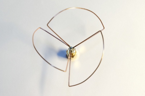
The hard part is to solder the short mounting taps on the side of the connector and then aligning all the three other ends on the center conductor.
