Audio power amplifier: Difference between revisions
From ivc wiki
Jump to navigationJump to search
No edit summary |
No edit summary |
||
| (8 intermediate revisions by the same user not shown) | |||
| Line 1: | Line 1: | ||
[[Image:Audio_amplifier_view.jpg|500px|right]] | |||
This was a electronics course project, building an audio amplifier based around the LM1875 op-amp. | This was a electronics course project, building an audio amplifier based around the LM1875 op-amp. | ||
== Report == | |||
* Project report: [http://beta.ivancover.com//electronics/ele103_effektforsterker_for_lyd.pdf Effektforsterker for lyd] - In norwegian, pdf | |||
== Circuit == | == Circuit == | ||
| Line 11: | Line 15: | ||
[[Image:Audio_amplifier_side.jpg|400px]] | [[Image:Audio_amplifier_side.jpg|400px]] | ||
[[Image:Audio_amplifier_overview.jpg|400px]] [[Image: | [[Image:Audio_amplifier_overview.jpg|400px]] [[Image:Audio_amplifier_bottom.jpg|400px]] | ||
== Measurements == | == Measurements == | ||
Measuring the input and output signal using a oscilloscope will verify if the circuit is designed correctly, which it turned out to be. | Measuring the input and output signal using a oscilloscope will verify if the circuit is designed correctly, which it turned out to be. | ||
Here the amplifications is about 25 (9.8V/0.4V). | |||
[[Image:Audio_amplifier_oscilloscope.png|400px]] | [[Image:Audio_amplifier_oscilloscope.png|400px]] | ||
Latest revision as of 19:38, 19 February 2011
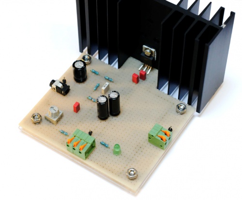
This was a electronics course project, building an audio amplifier based around the LM1875 op-amp.
Report
- Project report: Effektforsterker for lyd - In norwegian, pdf
Circuit
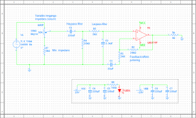
The circuit was constructed after calculating the amplification, upper and lower frequency band, according to the specifications.
Final
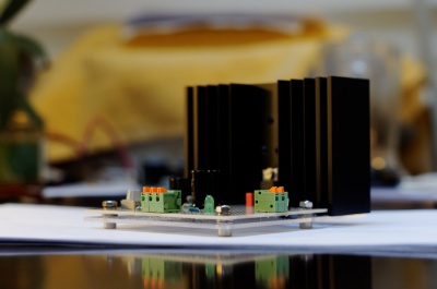
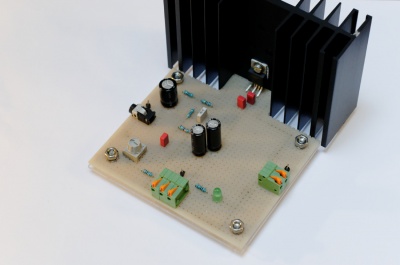
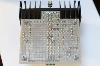
This shows the final circuit, mounted to a flexi-glass plate to balance the enormous heatsink and protect the bottom traces.
Measurements
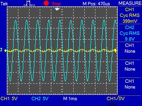
Measuring the input and output signal using a oscilloscope will verify if the circuit is designed correctly, which it turned out to be.
Here the amplifications is about 25 (9.8V/0.4V).
