Electric Bobby Car Build
This is the electric motor upgrade build log of a Bobby Car using two Hoverboard. The end result will have four motors, one per wheel, two Xbox 360 potentiometers as throttle and brake on the stock steering wheel, and two push buttons to turn on and off each controller separately (e.g. FWD, RWD, AWD). Inside the Bobby Car cavity, the controllers, battery, and cabling will reside.
Most of the front wheel steering assembly has been replaced by 3D-printed parts, which are available for download. The rear wheel base has been replaced with an aluminum mounting plate.
The controllers will be flashed to a new firmware developed by Larsmm which is a fork of NiklasFauth original base.
Base preparation
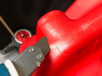
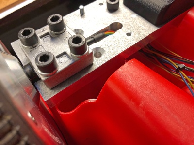
Main equipment slot
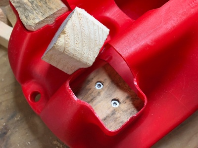
Slot had to by cut out of the base to allow internal access.
File:Electric bobby car build base cut internal slot1.jpg File:Electric bobby car build base cut internal slot2.jpg
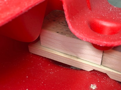
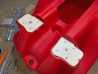
Two rear indentations were cut to insert the wooden base structure which later will be used to mount the aluminium wheel base plate. These are cut at the same height as the new front wheels, so the base is level. It is an advantage to prepare the back wheel base before cutting the slots.
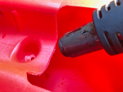
To remove sharp edges and to release stress areas, the cut edge was heat gun finished.
Rear wheel base
The rear wood stricture consists of one cross beam and six smaller wood pieces to fill the new slots. The load of the drive will nicely be distributed to the wheels and ground, increasing the max. driver weight to over 100kg.
Each wooden piece was fastened to the parent piece, making sure to use a different screw pattern for each layer to avoid conflicts.
Mounting the wooden structure to the plastic base was done by eight wooden screws through the side of the rear walls, linking each layer of the internal structure. Using washers to distribute the load as wide as possible.
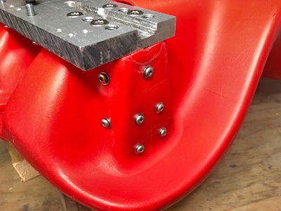
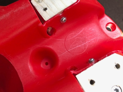 File:Electric bobby car build base rear mounting structure3.jpg
Rear wheels
All the parts of the stock front and rear wheels was removed, only a few of the front steering assembly parts will be reused.
Wheel base plate
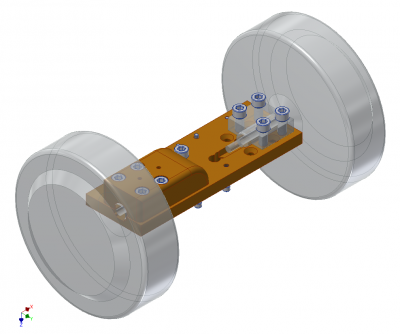
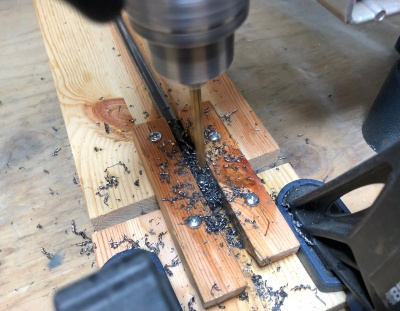
As much of the drivers weight will be over the rear wheels, the wheels will be mounted to an 200x70x12mm 6061 aluminium base plate. Slots and screw holes were routed and drilled/tapped out using regular home/garage gear. The design of the plate can be downloaded here.
File:Electric bobby car build wheels rear plate1.jpg File:Electric bobby car build wheels rear plate2.jpg File:Electric bobby car build wheels rear plate3.jpg
Mount wheels
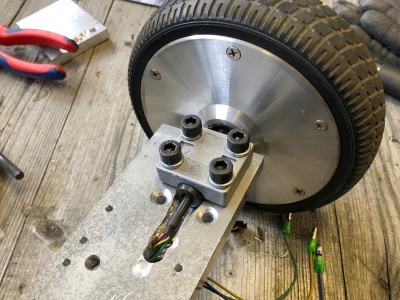
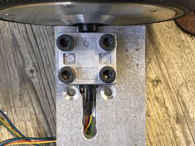
Both wheels are mounted to the base plate by sandwiching the axle between the stock Hoverboard bracket using four screws.
Axle cover
The axle and motor wires are directly exposed and could be damaged. A 3D-printed cover screws in place over this area.
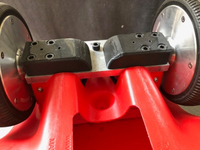 File:Electric bobby car build wheels rear cover2.jpg
Front wheels
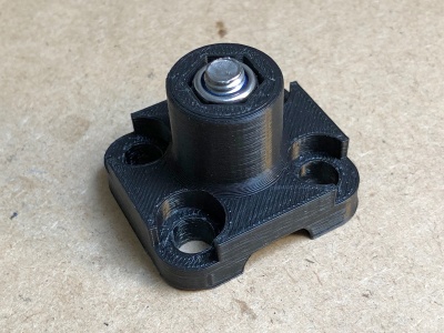
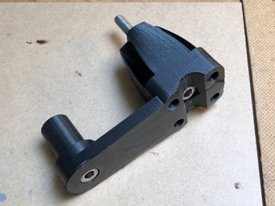
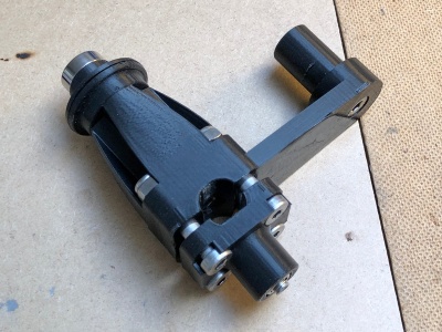
The front wheel assembly was modeled and new parts designed to incorporate the new motors into the front stock wheel structure. Wheel clearance height was increase by 15 mm to all the bigger radius Hoverboard wheels to fit. All parts were 3D-printed but strength was designed into the parts, primarily using long through screws to relieve much of the sheer stresses on the plastic.
Full aluminium CNC parts or metal support inserts would be a future upgrade here.
Wheel assembly
The assembly consists of three main parts and six screws along with six nuts to keep it all together. A skateboard bearing lessens some of the pressure and tear on the base plastic.
Wheel bracket
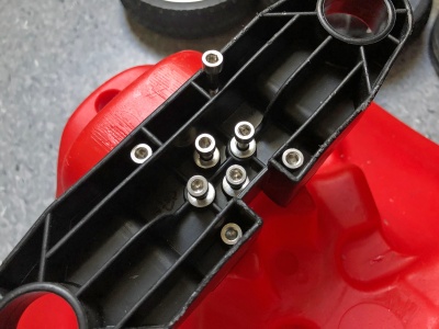
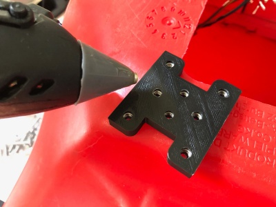
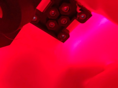
Both wheels are kept in alignment by the stock front wheel bracket. This is screwed onto the base frame. The bracket has been reinforced using eight screws with a counter plate instead of the stock two threaded screws.
Steering
Rod bend
To make the steering usable, the steering rod had to be lengthened by approx. 16 cm. The new rod was based on the stock dimension and bend, just longer on one end to put the steering wheel at a comfortable position.
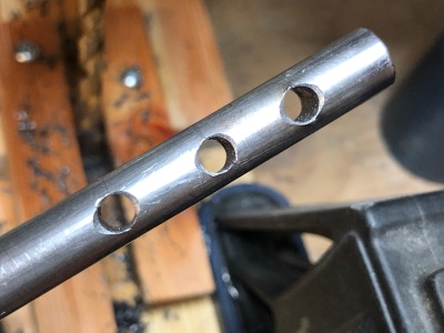
Using a Ø10mm stainless steel rod, one end was heated using a simple butane camping gas stove to heat the metal to make it pliable. Stick it in vise and bend it to the approx. radius. Then put the entire bend into the vise and squeeze it into the right dimension, using the stock as a template.
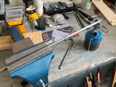
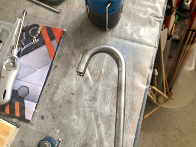 File:Electric bobby car build steering rod3.jpg
Rod length and mounting
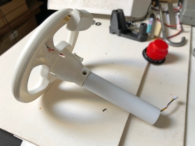
Try the rod on the Bobby Car with the steering wheel next to it to find the correct steering height, approx. +16cm on the stock length. Mark the spot and cut the rod. To allow for different steering wheel heights, I made three different mounting holes. This also requires a through hole in the plastic on the steering wheel.
To keep the rod from falling through on assembly, an outer Ø32mm white PVC tube keeps the steering wheel at the correct position and protects the wiring going to the controller.
Base rod support
As there will be a lot of load on the steering rod, so additional support has been added to the top and bottom side where the rod protrudes through the base.
File:Electric bobby car build steering rod support1.jpg File:Electric bobby car build steering rod support2.jpg File:Electric bobby car build steering rod support3.jpg
Throttle and brake
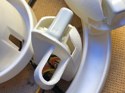
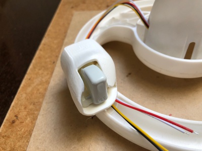
Using NiklasFauth method for the throttle and brake levers by mounting them on the front side on the steering wheel. A special 3D-printed holder keeps the trigger, potentiometer and support board in place. All put in place on the steering wheel using hot glue.
Electronics
Motors
Controllers
Battery
Power buttons
Power plug and charging
Flash firmware
References
- Larsm Allrad e-Bobby Car - great write up and custom firmware fork
- Niklas Fauth Hoverboard firmware hack - original firmware
- CCC GPN18 HowTo: Moving Objects - great talk
- Build Instruction: TranspOtter - Another build, lots of helpful pictures
- Fisch's detailed build guide - great documentation of the assembly
- Fisch's trailer build - trailer for the Bobby Car
- Jan Henrik breakout boards - PCBs for easy connection to serial and Nunchuck
