AXN Clouds Fly Setup
My preferred setup of the AXN Floater Jet.
Vertical Stabilizer
Glue the stabilizer in place using the supplied adhesive glue. Make sure it's in line with the canopy hook in front when looking from the back.
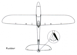
Flex the rudder back and forth to loosen up the foam hinge. The less force needed to move the rudder the less stress is put on the servo during flight. Alternatively cut them off and use clear packing tape to re-attach them, one slice on each side.
Rudder
- Push-rod: 1 mm
When using the stock horn set and push-rod, attach the horn set to the rod before clipping the horn to the rudder. The other way around will very difficult as the insertion angles will conflict.
A better method is to add a snap-style clevis between the horn and push-rod. This way it's possible to repair and disassemble the rudder and elevator easily. The stock Z-bend has to be straighten to a L-angled shape to work.
For maximum throw, use the lowest inner-most hole on the rudder horn and the outer-most on the servo arm. The stock servo arm already has a larger hole for the push-rod connector located close to the end. When replacing the servos make sure to pick the arm with the greatest throw and most number of holes.
Center the servo by connecting the receiver/transmitter and put servo arm in the middle of the travel range. The servo arm will most likely not be dead center but a step to either side. Try another servo horn with two arms and flip them around until a suitable one is found. Cut the unused arm and sand down the edges.
Connect the pushrod to the pushrod snap/stop connector on the servo arm, position rudder in neutral and fasten the set screw. The excess pushrod sticking out should be cut off to avoid poking hole in something, e.g. battery.
Horizontal Stabilizer
To make the plane as transportable as possible, the horizontal stabilizer is kept detachable. By glueing two hooks, I used low-profile aileron horns, on each side of the vertical stabilizer and using a 3x10mm rubber band around the front of the vertical stabilizer, it is kept sufficiently secure by the suspension. To avoid that the stabilizer is flipped up by the rubber band, add two small pieces of plastic to both sides of the vertical stabilizer where the front edge of the horizontal stabilizer meets up.
During fast dives the elevator could deflect or temporarily flex, by making a groove and gluing a 3 mm carbon fiber rod in place from tip-to-tip will increase the load strength.
File:Floater Jet elevator rod.jpg
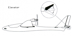
As with the vertical stabilizer, flex the elevator hinge to loosen up the foam.
Elevator
- Push-rod: 1 mm
For easy repair and disassemble, use the same snap-style clevis as mentioned on the rudder.
Wings
The main wings comes with servos pre-installed and one glass fiber tube cover glued in place. To make it easier to remove and replace the servos I cut away a 2 mm thin foam slit along the length of the tube cover. The servo cable can then passed and tucked down into the canal.
Glue the other cover in place using the supplied adhesive glue. Sand down each end of the glass fiber tube slightly to make the insertion go smoother. I like to only insert the tube in the wings without any additional glue. This makes it easy to transport the plane and replace the tube if it should break.
To keep the wings together during flight, add two hooks to the underside of the wings and use a thick rubber band to force the wings against each other. Another possible method is to fit reasonably strong magnets or velcro.
Aileron
- Push-rod: 1 mm
For maximum throw, the aileron wing servos has to be swapped around vertically. The servo head should be pointing toward the back instead of the leading wing edge. The easiest way is to swap the left wing servo with the right, that way the adhesive double-sided pad stays on the same side (bottom).
Connect the servos to the receiver and power on the transmitter to center the servo arm. If the transmitter can be programmed, configure the throw, also called travel adjust, to 140%. Try moving the aileron stick and make sure the servo arm does not hit either side, any binding will quickly wear out the servos and strain the BEC transistors on the ESC.
Battery
- Hyperion 3S 1300 mAH 25C 35x71x23mm 103grams Lipo
- Moxie S3 1800 mAh 40C 35x103x21mm 164grams Lipo
- Hyperion 3S 2100 mAH 25C 34x107x23mm 166grams Lipo
- Moxie 3S 2200 mAh 30C 36x102x26mm 198grams Lipo
To make a 2200 mAh Lithium-ion Polymer battery fit under the canopy and balance correctly, remove 3 mm foam on each side (6 mm total) of the centre canal using a hobby knife. It should be possible to move the battery all the way forward in the nose section.
I changed all the connectors to Deans T-type. They provide a firm connection and large contact surface, making them ideal for high current applications.
Transmitter
- Spektrum DX7 2.4 GHz Mode 2
- 7 Channels
- User manual
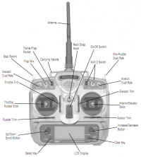
This transmitter has 7 channels is programmable for both airplanes and helicopters. It has a 3-way flap switch, aileron and elevator dual rate switches, rudder mix switch, gear and aux2 switch. A preset memory makes it possible to set up several different models on the same radio.
Settings (other than defaults):
- Travel Adjust: THRO Low 102% - To make the motor stop on low thottle
- Aileron-to-Rudder mix: Rate 40% - Faster rolls
Receiver
- HobbyKing AR6110B DSM2 Compatible 2.4 GHz receiver
- 6 Channels
- User manual
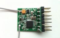
This is an excellent 6 channel tiny 4 grams receiver with signal path diversity. It comes bare but the case can be downloaded and printed. Add some foil to the inside panel of the case to make it even more immune to RF-noise.
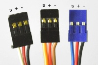
Negative lead is the top pin, as opposed to the Spektrum receiver which is reversed. This means the brown or black wire of the 3 wires must face up. Accidently reversing the connector does not harm the receiver as the 5V power is the middle pin and won't short the circuit.
Mount the receiver in a location where the antennas can be 90 degrees perpendicular to each other, e.g. the vertical surface in cockpit over the elevator and rudder servos or in the bottom space of the fuselage.
Hook-up for 4 channels: (Looking from the top, pins to the right, from the bottom)
- BAT/Bind - Only used for binding
- THRO - ESC throttle control and 5V power
- AILE - Aileron Y-cable
- ELEV - Elevator servo
- RUDD - Rudder servo
- GEAR - Unused - Can be used for elevator or aileron gyro gain
- AUX1 - Unused - Can be used for full aileron control, e.g. flapperons or spoilerons
Hook-up for 5 channels, full aileron control:
- BAT/Bind - Only used for binding
- THRO - ESC throttle control and 5V power
- AILE - Aileron servo left
- ELEV - Elevator servo
- RUDD - Rudder servo
- GEAR - Unused - Can be used for elevator or aileron gyro gain
- AUX1 - Aileron servo right
A little cool quirk I was surprised by, the ESC beeps are actually coming from the motor. Feeding short pulse burst to the motor dissipates as sound, cool!
ESC
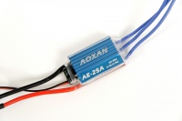
- AOXAN AE-25A Programmable ESC - Not compatible with programming card
- Linear BEC 5V 2A supply, two AZ1117D 1A FET-transistors in parallel
- Soldered directly to motor, Deans T-type battery connector
- User manual for Align RCE-BL15X ESC - Similar setup but without the BEC voltage option
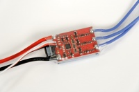
This is the included speed controller. It originally was a 20A unit but the manufacturer bumped it up the 25A after user reports of excess heat development. It seems to be a clone of the Align RCE-BL15X, at least it has the same setup mode. There's also a Turnigy AE-25A that looks exactly the same. Programming it requires manual setup using the throttle stick procedure, it's not compatible with the HobbyWing or Turnigy Programming Card.
Add 3.5 mm or smaller bullet connectors to the 3 motor wires for easier maintenance and ESC/motor replacement. Requires soldering of 6x connections, 3x ESC female connector and 3x motor male plug. Put 4 mm shrink tube on all excessively exposed surface.
Mount the ESC in a location with some airflow, e.g. in the nose section or the bottom space of the fuselage. It might be necessary to extend the motor silicone wires (18 AWG) or the battery wires (16 AWG).
Configuration can be done by setting throttle to full when powering the ESC, after the initial two up-down beeps, set throttle stick to low, another two up-down beeps and main settings can be configured in sequence. Setting number one will have 5 beeps of 1 short beep, number two 5 beeps with 2 short beeps, and so on. A configuration beep is heard at the end of each setting. The position of the throttle stick determines the option to be set. See the user manual for a table of the options for all the 5 settings.
The throttle range is set in the initial step when entering setup mode. If you ever enter the setup mode accidentally, make sure to complete all the 5 settings.
Settings:
- Brake: Soft break - Stick middle
- Electronic timing: High timing - Stick full
- Battery protection: High 3.2V cut-off voltage - Stick low
- Aircraft: Airplane/glider (no soft start or governor) - Stick low
- Throttle response speed: Quick speed - Stick high
Motor
- Motor: 2208N 2100KV brushless outrunner
- Current draw at 5x5 propeller, 3S battery: 18A
- Mount: 9 mm tube mount
- Bolt pattern: 16x16 mm
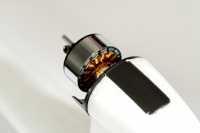
The stock motor is quite powerful and very suitable for this airplane. It's pre-soldered to the ESC. A large plastic mount with extended grip on top is glued to the motor pylon.
Some motors might develop a problem with the magnets shifting from their position. Some magnets might have insufficient Epoxy glue to hold them in place over repeated use. Do an inspection and if necessary add small amounts of clear Epoxy glue into the slots around the entire barrel. This is to keep the mass when spinning around the center balanced.
Propeller
- Stock EMP 5x5 propeller
- APC 6x4E propeller
- TGS 6x4 Sport propeller
For optimal fight performance and efficiency the most suitable propeller seem to be 6x4, e.g. diameter 6-inches and travels 4-inches per rotation. For higher top speed try a 6x5 and better acceleration a 6x3.
The stock 5x5 will work fine, but compared to the 6x4, will run with higher rpm and lower thrust. Try the Webocalc propeller site to the theoretically most suited esc/motor/propeller combination.
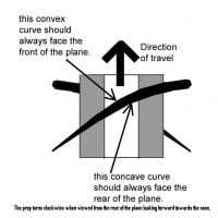
A balanced propeller is essential, use a magnetic bearing propeller-balancer. Either add thin tape to the backside of the lighter blade or sand down the back of the heavier blade. The back is the concaved side, bending inwards.
There are two ways to mount the propeller to the motor.
- Prop-saver - Use a o-ring rubber band around two grub screws, this is the stock mount
- Collet-adapter - A bushing ring clamped on the motor shaft by a spindle and compression nut
The stock prop-saver is OK but the propeller can vibrate and the o-ring wear out. A properly balanced collet-adapter should be more durable and produce less vibration, thus fly better and quieter.
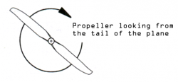
Mount the propeller with the concaved side facing the tail of the plane. Using the stock, or any other regular propeller, the text should face the toward front of the fuselage.
Using the collet-adapter, break away the smaller 4.8 mm adapter ring and sand or cut away the excess plastic tabs. Use medium thick CA glue to fix the ring to the propeller. The ring should be flush against the propeller surface. Mount the propeller and if the blades hit the adapter before the actual center of the propeller, cut away a bit of the plastic or, preffereabily, add a spacer between the adapter and propeller.
For the prop-saver method, use the adapter ring closes to 3.0 mm and use a plier to squeeze a little to minimize the small flex in the ring. Use CA glue to fix in place. Mount the propeller in the correct orientation, normally with the text front and the adapter ring rear. Strap the o-ring over one of the grub screw and over the propeller to the other grub screw, no crossing necessary (center of mass).
Center of Gravity
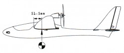
- CG from LE: 51.5mm
An intricate measure for achieving excellent flight characteristics is center of gravity (CoG or CG). The CG should be right in the middle of the tube spar cover under the wings. Measured from the leading wing edge it's 51.5 mm back.
The usable CG range seem to go from 49 til 56 mm. Setting CG farther back (up to 56 mm) will put the plane in the sweet spot for minimum drag, the lowest point of induced drag (wing lift produced with the least drag at the airspeed with the lowest angle of attack ) and the least parasitic drag (resistance created by moving through the wall of air or fluid at increased airspeed) [1]. This point is optimal for a glider. Moving the CG forward (down to 49 mm) will decrease the induced drag (lower angle of attack and decreased wing lift) and allow for faster airspeed.
Balance the plane on two sticks and make sure the balance point is the same for each wing. Adjust the CG by moving the battery back and forth or moving the receiver or ESC around. That last resort is the add dead weight, but try a bigger battery first (1800, 2100, 2200 mAh) to get something useful out if the extra weight. When the perfect balance is found, mark spots for the balance point under the wings and the position of the battery for quick reference and configuration.
Pre-flight Test
Before each flight, do something like the following procedure to avoid simple mistakes.
- Check the Lipo-battery voltage, fully charged 4.20V per cell and on 3S 12.6V total
- Turn on transmitter, low throttle stick, check Tx battery voltage, switches and trims
- Check the propeller, concaved side facing rear, servos secured in place, control horns properly mounted
- Apply power to plane, balance battery on preferred center of gravity point
- Secure battery, tidy up area around internal servos for free movement, fasten canopy
- Stand behind the plane:
- Move aileron stick to the left, aileron on left wing should deflect down and the right aileron up
- Move elevators tick down, elevator should deflect down
- Move rudder stick to the left, rudder should deflect to the left
- Move throttle stick up slightly, motor should start to rotate clockwise
- Do radio range check if necessary and plan several spots suitable for landing
- For increased lift/angle of attack during launch, trim or flip programmed switch for a little elevator up
- Stand against the wind, apply half throttle, hold plane 20-30% up, throw hard, second later trim down elevator and go!
