LED Bandwidth Monitor
After discovering how cool RGB LED strips are, I decided to make a bandwidth monitor for the Internet connection at our place. Since there are many users active on the same connection there's bound to be conflicts where someone is gaming and another is downloading, causing the ping to fluctuate (even with QoS HTB-init set up).
I discovered the strips over at the Adafruit blog, check this Adafruit Ask an Engineer video (starting at 3:23) for details.
LED Strips
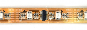
One meter of LED strip has 32 LEDs, where for each section is 2.5 inch (6.35 cm) and consists of one shift-register controlling two LEDS. There is also a bypass capacitor and current-limiting resistors. Each LED has 6 pins, grouped in pairs for each of the 3 primary colors. One reel is 5 meters and comes with end connectors already soldered on.
The strip is housed in a rubber casing and when the ends are sealed can be made waterproof.
Controlling
File:LED Bandwidth Monitor hl1606.jpg
The shift-register is a HL1606 with A and B channel, fading capability, 5V, SPI-like device. Adafruit has two Arduino libraries up, one plain and one using PWM. The latter allows dimming of the three primary colors to display 3, 4, or 5-bit color.
- Adafruit HL1606 LED Strip - Arduino lib
- Adafruit HL1606 LED Strip PWM - Arduino lib
Bandwidth Monitor
The data is feed from the gateway using the bwbar utility for Linux. It outputs a text file every other second which is picked up and parsed by a shell script. The values are then passed over the network to an Arduino with an ethernet-shield using wget.
A simple GET-http request with the values is sent to a basic webserver listening on the Arduino. Once the values are parsed to integers, they're transferred over I2C/TWI bus to another Arduino.
The second Arduino is the LED driver and is responsible for driving the strip. It had to be on a separate device because the ethernet-shield requires SPI, as does the LED strip, and there's only one hardware SPI interface. It might be possible to put everything on one device and address ethernet and the strip when needed, but I decided it was too time consuming to look into at the moment.
Download the Arduino source code:
- Download Web Server Interface
- Download LED Driver - Requires the HL1606-LED-Strip-PWM Arduino library to be installed
Power
A 5V 2.5A powersupply is powering the LEDs and the Arduinos. The maximum driving current for one LED section is unknown, but the Adafruit product page states 120mA for 2 LEDs including the HL1606 (which seem a bit high to me).
I have yet to measure the actual current drown.
Mount
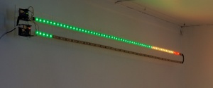
I wanted to make the monitor bars to be huge and as long as possible to get satisfactory resolution. To fit the space on the wall, I ended on the final dimension of 2 meters long and 15 cm height. That's 2x64 LEDs for download and upload monitor bar.
To mount the LED strips, I first made a 2 meter long base plate out of 10 pieces of 15x20 cm plexiglass plates glued together using regular CA-glue. Drilled holes for each 20 cm section, pulled fishing string through the holes, put double sided adhesive padding next to the holes, and tighned the string to get a firm fit. Remember, the LED strips will hang vertically and gravity will pull the strips down.
Using 4 hooks and double feed of fishing string, the entire plate with the two Arduino devices and LED strips is lifted into place. The assembly is hanging 8.5 cm away from the wall.
The only wires connected to the assembly is 5V power and an ethernet cable connected to a switch.

