Solar Panel Charging
Basics about solar panel battery charging setup.
Equipment required
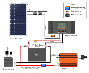
To set up a nice and compact DC solar charging and distribution network, the following gear is required:
- 1x 100W/18V (12V) Monocrystalline Solar Module
- 1x 10A 12V/24V MPPT solar controller
- 1x ABS solar module fix frame work.
- 1x 3M MC4 male/female connector solar cable
- 1x 6M Solar cable
- 2x 10A Fuse weatherproofed
- 1x Breaker on/off 10A - after panels
Panels
Monocrystalline panels are regarded as being the most efficient panel technology. Second to Polycrystalline panels. In, 2016, Sunpower is considered to have the best solar cell technology, they are also used on the Solar Impulse aeroplane.
Common configurations of individual panels (complete cells):
- 100W - common
- 120W
- 150W - common
- 160W
- 300W
- 320W - common
Each panel is an array of cells, a 100W panel can have 32 cells, where each has a nominal voltage of 0.57V@5.83A. That gives us 32x0.57V=18.24V, and the total power output is then 18.24Vx5.83A=106.34W
Arrays are usually built by parallel installation of multiple of the same panel type, e.g. 10x150W panels is a 1500W or 1.5kW array.
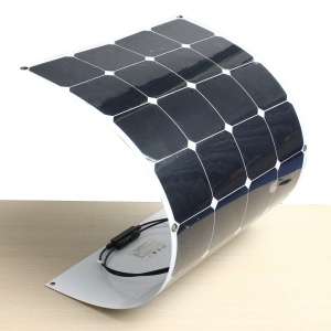
Some cheap flexible panels:
- 100W 18V Mono panel - 137USD
- 100W 18V Mono panel - 116USD incl. shipping
- 100W 18V Mono panel - 117USD incl. shipping
Building solar panels
It is possible to build a large solar panel from scratch. You only need to get the individual parts, which is really not that much or hard to put together.
Kits:
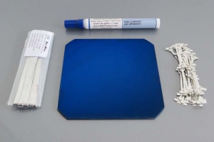
- DIY 100W Sunpower Maxeon C60 Solar Panel 21.8% Efficiency - 32pcs x 3.34W
- Sunpower Maxeon C60 Solar Cell 10pcs with 10pcs dog bone wires
Different parts of the system:
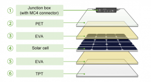
- Solar Cell - photovoltaic module, converts sunlight to electric current, provides approx. 0.5V each
- Typical cells: 6x6-inches at 4.8W, 5x5-inches at 3.2W
- Solar Tabbing Wire - connects modules into strings - multiple cells connected together, e.g. 9 cells provides 4.5V (0.5V x 9)
- Bus Wire - forms an "S"-shape and connects the strings into an panel, e.g. 4 strings provides 18V (4.5V x 4)
- Flux Pen - makes it easier to solder the tabbing and bus wire
- Encapsulation Film - seals the front and back of the solar cells in a vacuum, e.g. EVA 0.3mm film, essentially hot glue
- Backing Sheet - works as an insulator and protects the back of the panel, usually a multilayer laminate, e.g. TPT Tedlar 0.3mm film, essentially a waterproof sheet
- Mounting Frame - makes it easier to mount the panel to a roof or other installation infrastructure
- Junction Box - connects the two bus ends to screw terminals
- Cable - makes it easier to weatherproof and connect multiple panels together, e.g. in series (higher voltage) or parallel (more current)
- Diode - when panels are installed in parallel and one is damaged, a bypass diode allows the other panels to still work, also blocks reverse current flow, installed in the junction box
Solar controllers
There are two kinds of controllers; MPPT (Maximum Power Point Tracking) and PWM (Pulse Width Modulation) charging mode, with the former being the preferred one. The MPPT circuit is based around a synchronous buck converter circuit. It steps the higher solar panel voltage down to the charging voltage of the battery. PWM is suitable when the solar panel voltage and battery charge voltage is close.
- PWM - good when panel and battery charge voltage is approx. the same level, e.g. 15V panel charging a 12V battery at 15V, higher panel voltage is just not used efficently
- MPPT - extracts the most out of the panel regardless of how the panel and battery charge setup, e.g. 24V panel charging a 12V battery at over 98% efficiency
A reasonable decent solar controller starts at 50USD, for a 10 to 30A 12V setup. A 30A controller can handle up to 30 x 12 = 360W of solar panels connected to the input.
Commercial:
- Xantrex PWM solar charge controllers - commercial controllers and meters
PWM:
- Morningstar ProStar 30A PWM 12/24V charge controller - Quality, reliable
- Zamp Solar 15A PWM controller - Good quality controller [1]
MPPT:
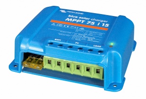
- Victron Energy BlueSolar 100V/15A MPPT charge controller - Professional quality, ultrafast tracking
- EPSolar Tracer 20A 2215BN or 30A 3215BN - Good quality components, somwhat long tracking time (>1min) [2]
- EPEver Tracer 3210A 12/24V MPPT charge controller - Value controller, external display [3]
- ECO-Worthy 20A MPPT 12/24V solar charge controller - Good controller, MPPT in bulk charge, PWM in float, fast tracking, china clone [4]
Batteries
Using regular 12V or 24V batteries makes it simple to get set up. It is preferred to use deep cycle branded batteries because these are have thicker plates and are designed relatively low continuous power draw.
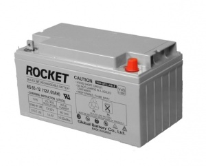
- AGM (Absorbed Glass Mat) 12V lead acid battery - recommended type for solar, can hold 300 cycles when kept above 50% discharge rate
- Gel cell 12V lead acid battery - suitable for very deep cycle operations and hot environments [5]
Models:
- OPTIMA Group 31 batteries
Inverter
If there is any equipment or appliances that require 110/220V AC power, an inverter will convert 12V DC to AC power you need. The main parameter that dictates the kind of inverter you need is the wattage rating, e.g. a MacBook charger is 85W and then you require a 100W or better inverter to power it properly (under 10% loss presumed).
The second parameter to consider is operation mode, if it is going to supply power back to the power grid, called grid tied (requires certified installation), or a simpler independent car type inverter.
- Inverter 110/220V 100 to 3000W stationary or grid tied
For optimum efficiency (minimized power loss in conversion), always try to power or adapter the equipment from DC directly. The chain of the energy flow is as follows:
Solar rays -> Solar array -> Charger controller -> Battery -> Inverter -> Equipment
                                                           -> Equipment
Cables
The standard solar cable wiring separates the positive (+) and negative (-) leads. This makes it easier to series connect multiple panels. For parallel it does not make much differences, or rather, makes it more cluttered.
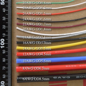
Solar panels always produce DC current, therefore the wire gauge dictates how much loss you will have over a longer cable stretch. Thicker cables means lower loss, thinner more loss. Always use multi-fine stranded cables, these are flexible and carry more current than single-core (AC) cables.
Cable types for solar installation:
- Tray cable/USE1/USE2 - outdoors, nylon for extra strength, most common [6]
- Boat/marine cable - for junction wiring
The wire gauge/thickness for the different parts of the system essentially breaks down to the following. If you series connect panels the voltage multiplies but the current stays the same, and you can keep using the same cables, but if you expand in parallel the current multiplies and you have to re-dimension the backbone current carrying cables to take the extra load.
The general rule when it comes to DC wire gauge management is larger/thicker is better to minimize voltage drop.
General recommendation:
- 8 to 10AWG - for backbone distribution from solar array to controller box, inverter and battery [7]
- 10 to 14AWG - for panel leads, smaller loads such as DCDC converters, fridges, fans
Check this table for distance in feet.
Here's a handy equation [8]:
voltage drop = round(systemvoltage*alloweddropprocentage)
awg = round(10*(ln(voltagedrop/100/(wirelength*current))*0.434)+37)

F.ex
voltage drop = round(12*0.02) = 0.36V
awg = round(10*(ln(0.36/100/(45*1))*0.434)+37) = 14AWG
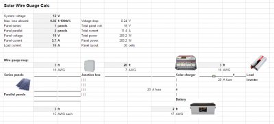
To make the overall system cable calculation easier, I've made a
- Wire gauge calculation - sheet, where you just need to input your system specs and length of the different cables
- Victron Energy MPPT calculator - useful to check basic layout
Circuit breakers/fuses
An important part of a safe solar installation are circuit breakers and fuses. They are installed in between major modules in the system, e.g. solar array and controller, battery and controller, and battery and inverter.
- Blade Fuse with in-line socket
- Resettable-fuses
Complete kits
These are fully integrated kits with mostly plug&play functionality. Great for a basis and upgrade the panels later on.
