Maglite Laser: Difference between revisions
(New page: A normal DVD burner laser diode is rated 200-300 mW and compared to the regular 5 mW laser pointer, it is a lot more powerful and potentially dangerous. '''IMPORTANT: Please read the lase...) |
No edit summary |
||
| Line 31: | Line 31: | ||
[[Image:Maglite laser diode pcb.jpg|400px]] [[Image:Maglite laser diode clean.jpg|400px]] | [[Image:Maglite laser diode pcb.jpg|400px]] [[Image:Maglite laser diode clean.jpg|400px]] | ||
[[Image:Maglite laser diode front.jpg|400px]] [[Image:Maglite laser | [[Image:Maglite laser diode clean front.jpg|400px]] [[Image:Maglite laser diode clean back.jpg|400px]] | ||
== Diode Mount == | == Diode Mount == | ||
Revision as of 22:07, 15 March 2008
A normal DVD burner laser diode is rated 200-300 mW and compared to the regular 5 mW laser pointer, it is a lot more powerful and potentially dangerous.
IMPORTANT: Please read the laser safety instructions and regulations before working with lasers, Wikipedia or Felesmagus
Extract Laser Diode
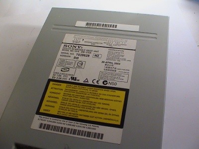
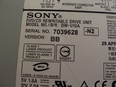
The DVD burner I used was an old Sony DW-U10A 4x model with a Class 1 laser.
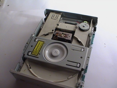
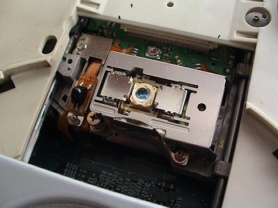
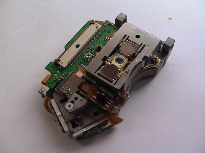
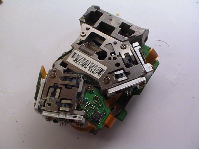
Remove the cover and get to the two tracking rails holding the laser unit.
The laser unit has two lasers, one for DVD and one for CD (correct?). It's hard to tell the two apart and the easiest way is to try one and then the other.
Be aware that some lasers do not beam visible light and can still damage your eyes [1]. Always beam away from you with no reflective areas around.
The hardest part of the project is to get the laser diodes out of the heat sink. The diode is normally glued and hard to press out. I had to bend the aluminum with a plier and crack the heat sink at the weakest points.
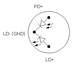
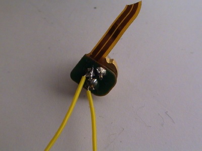
Solder two wires to GND and LD+, the third is not used and is for a optional photo diode. Use a single AA battery to try the diode, always do this away from you and not looking at the diode.
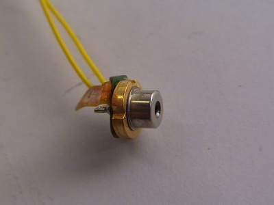
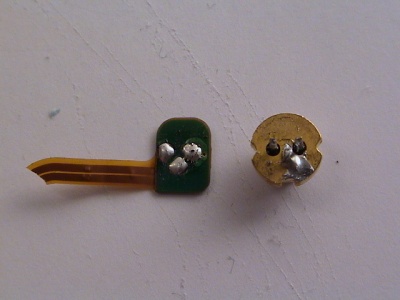
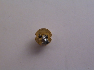
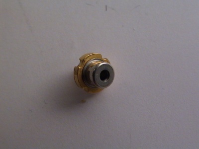
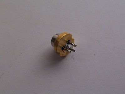
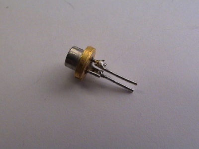
Now remove the PCB and clear up the diode.
Diode Mount
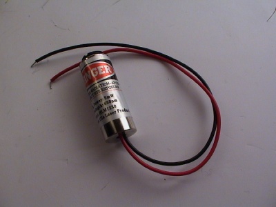
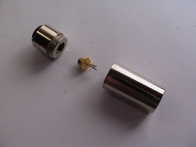
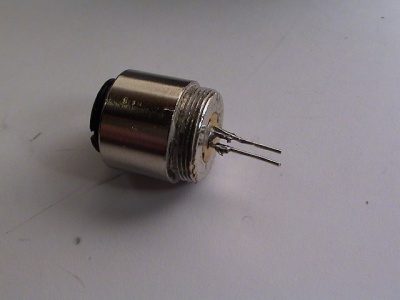
To mount the diode in the maglite, find a suitable housing case to fit the 5.6 mm laser diode. I used a 5 mW from AxiZ.
Remove the old laser using a plier or screw driver.
The front of the Axiz housing is the focus ring and is used to tune the laser later.
The diode will become warm after even a few minutes of use. Artic Silver 5 therman grease will help the thermal transfer.
File:Maglite laser artiv silver.jpg 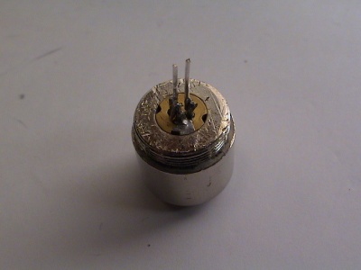
The pins on the diode is too short and needed to be extended.
Maglite Preparation
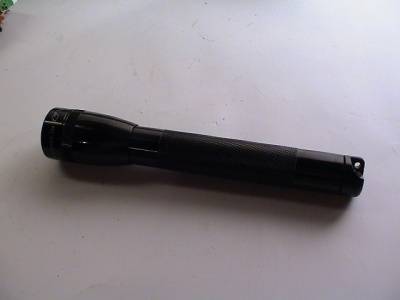
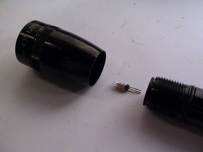
The Maglite is a AA model with a screw ring to turn it on and off. Without the front screw ring/reflector/glass the light is always on.
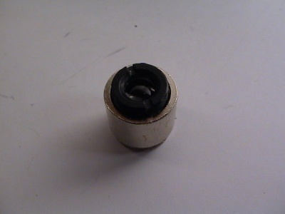
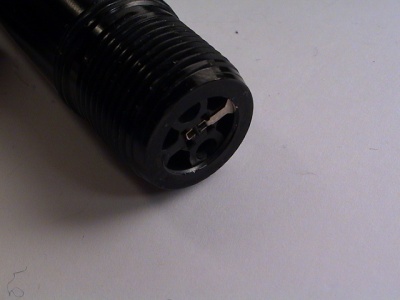
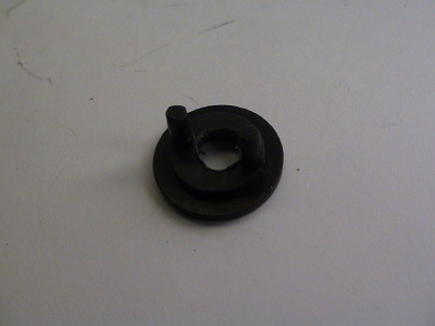
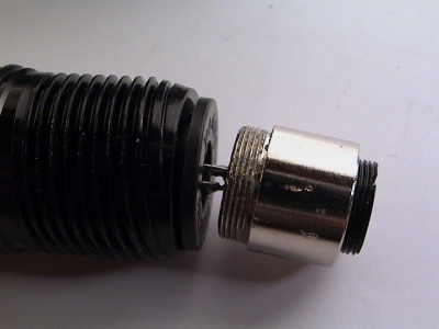
Under neath the black ring is the positive and negative poles, the one to the right is negative. The hole in the middle of the black ring has to be widened to fit the diode pins.
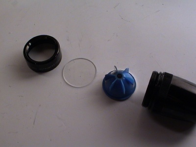
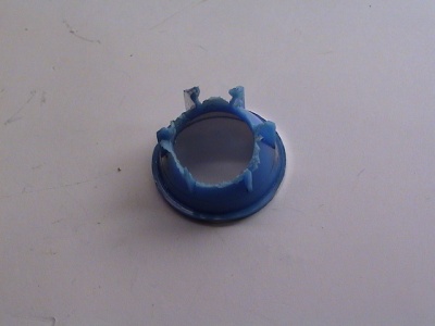
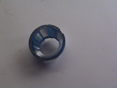
The reflector also needs to be widened to fit the Axis housing. I used a massive drill and drill-bit, but a Dremel would be better.
Assembly
The diode is mounted with extended pins and the Maglite is modified to fit the housing. Remove the batteries from the Maglite now!
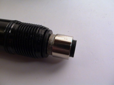
Put the pins into the socket of the Maglite body and put the batteries back. Be careful from this point on! Use the focus ring to find the fine point of the beam. Avoid looking extended times at the reflected dot.
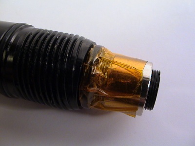
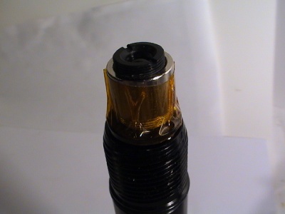
To avoid the pins to be twisted, I applied a single round of Kapton tape. It is highly adhesive and good for electronic use.
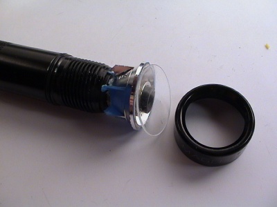
Put top back on. The top screw ring is composed of the top ring, glass, and modified reflector.
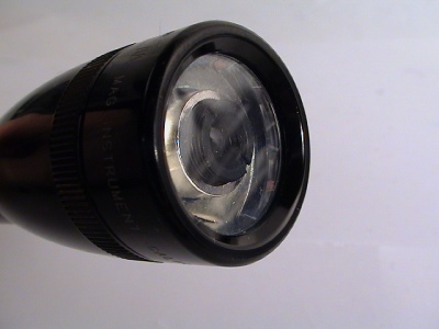
Once everything is put together and the screw ring is fastened, the laser housing focus ring should fit just underneath the glass.
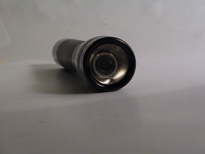
Only use this to learn how lasers work, remove the batteries when not in use and mark the Maglite of the laser danger.
