FrSky DHT RSSI configuration: Difference between revisions
| Line 12: | Line 12: | ||
== RSSI configuration == | == RSSI configuration == | ||
The DHT provides a serial data port for configuration of the alarms for the RSSI and the two analog inputs. Download the [http://rc-miskolc.emiter.hu/index.php?option=com_content&view=article&id=114:frsky-setup-program&catid=35:tech&Itemid=113 3rd-party configuration program] and the required [http://www.frsky-rc.com/download.asp drivers]. | The DHT provides a serial data port for configuration of the alarms for the RSSI and the two analog inputs. Download the [http://rc-miskolc.emiter.hu/index.php?option=com_content&view=article&id=114:frsky-setup-program&catid=35:tech&Itemid=113 3rd-party configuration program] and the required [http://www.frsky-rc.com/download.asp drivers]. | ||
RSSI alarm configuration: | |||
* '''High alarm: 40 dBc''' - final alarm, signal drops off under 38 dBc | |||
* '''Mid alarm: 49 dBc''' - precautions alarm | |||
[[Image:frsky_config.png|500px]] | [[Image:frsky_config.png|500px]] | ||
Revision as of 15:35, 19 August 2012
The FrSky DHT is a flexible and relatively powerful 2.4 GHz transmitter. The kit comes as a DIY package with an RP-SMA connector which makes it easy to switch antennas. The communication is two-way allowing for both Tx and Rx signal strength indication (RSSI). The ACCST system shifts 80 channels around hundred times per second in the 2.4GHz band, similar to FSK.
I will use an D6FR receiver in this setup.
Serial adapter
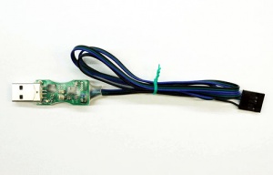
To connect to the transmitter you need a USB-to-serial adapter. FrSky makes one with the necessary pin-header.
Plug the black header into the corresponding four pins on the transmitter. Power will be provided by the USB-port.
RSSI configuration
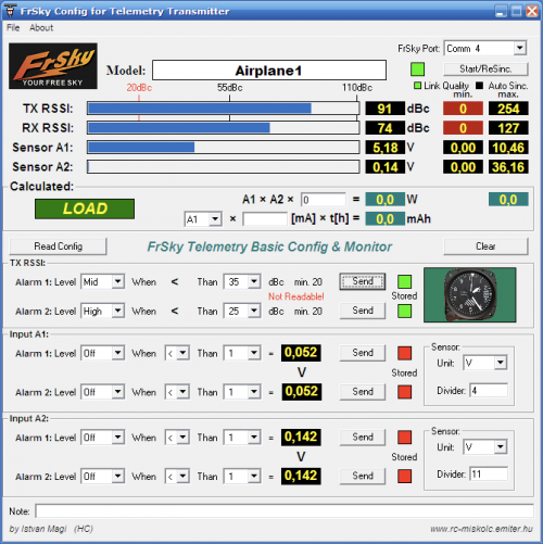
The DHT provides a serial data port for configuration of the alarms for the RSSI and the two analog inputs. Download the 3rd-party configuration program and the required drivers.
RSSI alarm configuration:
- High alarm: 40 dBc - final alarm, signal drops off under 38 dBc
- Mid alarm: 49 dBc - precautions alarm
Antenna testing
To get an idea of how well the different set of antennas would perform, I swapped the antennas one by one and recorded the Tx and Rx values from the configuration application.
All the tests where performed with a FPV VTX 1180 MHz without low pass filter running 20 cm away from the receiver and everything was done indoors with antennas about 12 meters apart in separate rooms.
- Transmitter: FrSky 2dbi rubber duck antenna
- Receiver: FrSky 2dbi rubber duck antenna - RSSI Tx: 37 - RSSI Rx: 66 - Without VTX Tx 62 Rx 70
- Receiver: Generic Alfa 5dbi rubber duck antenna - RSSI Tx: 52 - RSSI Rx: 71 - Without VTX Tx 67 Rx 71
- Receiver: Dipole 33 mm wire antenna - RSSI Tx: 41 - RSSI Rx: 74
- Receiver: Dipole 32 mm wire antenna - RSSI Tx: 49 - RSSI Rx: 73
- Receiver: Dipole 30 mm wire antenna - RSSI Tx: 62 - RSSI Rx: 78 - Without VTX Tx 59 Rx 70
- Receiver: Dipole 29 mm wire antenna - RSSI Tx: 54 - RSSI Rx: 74
- Receiver: Dipole 29 mm wire antenna - RSSI Tx: 54 - RSSI Rx: 74
- Receiver: Dipole 27 mm wire antenna - RSSI Tx: 51 - RSSI Rx: 74
- Receiver: Generic Alfa 2.4 GHz 14 dBi patch antenna - RSSI Tx: 73 - RSSI Rx: 79 - control
- Transmitter: Generic Alfa 5dbi rubber duck antenna
- Receiver: FrSky 2dbi rubber duck antenna - RSSI Tx: 37 - RSSI Rx: 54 - Without VTX Tx 62 Rx 71
- Receiver: Dipole 33 mm wire antenna - RSSI Tx: 52 - RSSI Rx: 78
- Receiver: Dipole 32 mm wire antenna - RSSI Tx: 41 - RSSI Rx: 74
- Receiver: Dipole 30 mm wire antenna - RSSI Tx: 57 - RSSI Rx: 77 - Without VTX Tx 64 Rx 73
- Receiver: Dipole 29 mm wire antenna - RSSI Tx: 49 - RSSI Rx: 74
- Receiver: Dipole 27 mm wire antenna - RSSI Tx: 54 - RSSI Rx: 68
- Transmitter: Generic Alfa 2.4 GHz 14 dBi patch antenna
- Receiver: FrSky 2dbi rubber duck antenna - RSSI Tx: 73 - RSSI Rx: 83 - Without VTX Tx 75 Rx 82
- Receiver: Generic 5dbi rubber duck antenna - RSSI Tx: 78 - RSSI Rx: 87 - Without VTX Tx 79 Rx 82
- Receiver: Dipole 33 mm wire antenna - RSSI Tx: 74 - RSSI Rx: 83
- Receiver: Dipole 32 mm wire antenna - RSSI Tx: 73 - RSSI Rx: 82
- Receiver: Dipole 30 mm wire antenna - RSSI Tx: 74 - RSSI Rx: 81 - Without VTX Tx 67 Rx 77
- Receiver: Dipole 29 mm wire antenna - RSSI Tx: 74 - RSSI Rx: 82
- Receiver: Dipole 27 mm wire antenna - RSSI Tx: 74 - RSSI Rx: 82
- Transmitter: Generic Dealextreme 2.4 GHz 14 dBi flat panel antenna
- Receiver: FrSky 2dbi rubber duck antenna - RSSI Tx: 73 - RSSI Rx: 82 - Without VTX Tx 76 Rx 82
- Receiver: Generic 5dbi rubber duck antenna - RSSI Tx: 78 - RSSI Rx: 85 - Without VTX Tx 79 Rx 85
- Receiver: Dipole 33 mm wire antenna - RSSI Tx: 73 - RSSI Rx: 81 - holding the panel 90 degrees to the side to match the vertical dipole polarity
- Receiver: Dipole 32 mm wire antenna - RSSI Tx: 73 - RSSI Rx: 82
- Receiver: Dipole 30 mm wire antenna - RSSI Tx: 72 - RSSI Rx: 80 - Without VTX Tx 75 Rx 82
- Receiver: Dipole 29 mm wire antenna - RSSI Tx: 76 - RSSI Rx: 83
- Receiver: Dipole 27 mm wire antenna - RSSI Tx: 74 - RSSI Rx: 82
As a side-note, the dipole wire antenna should have an exposed core with the length: 299792458/1000/2440/4*0.95 = 29.18 mm (speed of light/1000/middle of band/quater wavelength*velocity in conductor)
VTx harmonics interference
While the video transmitter was turned on, the harmonics caused the RC control signals to be attenuated. The list below shows the interference through all the 15 channels.
The test was done using a FrSky 2.4GHz rubber duck antenna on the transmitter and dipole wire antenna on the receiver, 12 meters apart. The video transmitter had a custom dipole antenna tuned for 1180 MHz.
Channel - Frequency - Rx RSSI - Tx RSSI
- no vtx 57 66
- 1 1000MHz 52 67
- 2 1020MHz 49 66
- 3 1040MHz 49 69
- 4 1060MHz 48 69
- 5 1080MHz 43 66
- 6 1100MHz 41 69
- 7 1120MHz 45 68
- 8 1140MHz 39 71
- 9 1160MHz 35 62
- A 1180MHz 35 61
- B 1200MHz 37 62
- C 1220MHz 39 60
- D 1240MHz 52 67
- E 1260MHz 52 67
- F 1280MHz 46 67
The bold outline shows the channels with the least interference. While the italic shows the channel with the most interference, coincides with the tuned 1180 MHz antenna.

