ESP8266 Controlled Door Operator: Difference between revisions
No edit summary |
|||
| Line 1: | Line 1: | ||
[[Image:Door_operator_swing_door.jpg| | [[Image:Door_operator_swing_door.jpg|350px|right]] | ||
At our office building, there is a Dorma [http://www.dorma.com/us/en/products/opening_closing/automatic_swing_door_operators/ed100_250_ansi/index-144-470-2757.html Automatic Swing Door Operator] which is normally engaged by a push button next to the door frame and also wirelessly from the hall way end of the door. | At our office building, there is a Dorma [http://www.dorma.com/us/en/products/opening_closing/automatic_swing_door_operators/ed100_250_ansi/index-144-470-2757.html Automatic Swing Door Operator] which is normally engaged by a push button next to the door frame and also wirelessly from the hall way end of the door. | ||
Revision as of 19:37, 21 November 2015
At our office building, there is a Dorma Automatic Swing Door Operator which is normally engaged by a push button next to the door frame and also wirelessly from the hall way end of the door.
Pressing and waiting for the door to open is unbearable, therefore I made the decision to add a third option to the mix; operating it wirelessly from my mobile phone using the web browser.
Digital switch
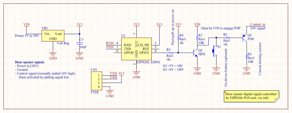
The way the existing wired and wireless buttons are wired on the automatic door operator is fairly simple, just ground and a control signal which is pulled high (24V). Pull this control line low and the door will engage and begin to swing open.
Adding a third option is just a matter of adding a transistor between the control signal and ground; and having a controller toggle the transistor when needed.
Schematic
The system is based on a 3.3V regulator (although I used my own ESP8266 breakout board which has a 3.3V regulator, connected to a 5V regulator capable of handling 24V in), the main ESP8266-ESP01 board and a pair of PNP and NPN transistors.
Build
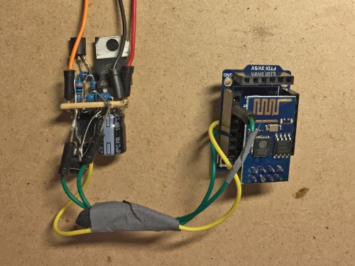
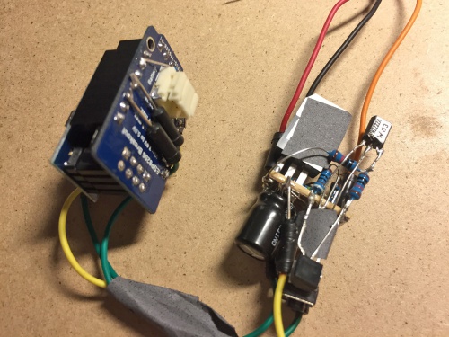
For this to be a one day build, I had to take some shortcuts to save time. The build is fully functional, but it might not look visually pleasing.
Code
The code is based on Lua for the NodeMCU firmware. Programmed using LuaLoader via a 3.3V FTDI USB adapter.
This code is based on a simple web server and modified to wait 500ms before releasing the pull-low toggleT.
wifi.setmode(wifi.STATION)
wifi.sta.config("WIFISSID","WIFIPASSWD")
print(wifi.sta.getip())
led1 = 3
led2 = 4
gpio.mode(led1, gpio.OUTPUT)
gpio.write(led1, gpio.LOW);
gpio.mode(led2, gpio.OUTPUT)
gpio.write(led2, gpio.LOW);
srv=net.createServer(net.TCP)
srv:listen(80,function(conn)
    conn:on("receive", function(client,request)
        local buf = "";
        local _, _, method, path, vars = string.find(request, "([A-Z]+) (.+)?(.+) HTTP");
        if(method == nil)then
            _, _, method, path = string.find(request, "([A-Z]+) (.+) HTTP");
        end
        local _GET = {}
        if (vars ~= nil)then
            for k, v in string.gmatch(vars, "(%w+)=(%w+)&*") do
                _GET[k] = v
            end
        end
        buf = buf.."HTTP/1.1 200 OK\nCache-Control: no-cache, no-store, must-revalidate\nPragma: no-cache\nExpires:

0\n\n";
        buf = buf.."<html><head><title>ESP8266 Srv</title></head><body><h1>ESP8266 Web Server</h1>";
        buf = buf.."<p>GPIO0 <a href=\"?pin=ON1\"><button>ON</button></a> <a

href=\"?pin=OFF1\"><button>OFF</button></a></p>";
        buf = buf.."<p>GPIO2 <a href=\"?pin=ON2\"><button>ON</button></a> <a

href=\"?pin=OFF2\"><button>OFF</button></a></p>";
        buf = buf.."</body></html>";
        local _on,_off = "",""
        if(_GET.pin == "ON1")then
          gpio.write(led1, gpio.HIGH);
          tmr.delay(500000);
          gpio.write(led1, gpio.LOW);
          elseif(_GET.pin == "OFF1")then
              gpio.write(led1, gpio.LOW);
              elseif(_GET.pin == "ON2")then
        	  gpio.write(led2, gpio.HIGH);
        	  tmr.delay(500000);
		  gpio.write(led2, gpio.LOW);
                  elseif(_GET.pin == "OFF2")then
                      gpio.write(led2, gpio.LOW);
                  end
                  client:send(buf);
                  client:close();
                  collectgarbage();
                  end)
end)
Installed
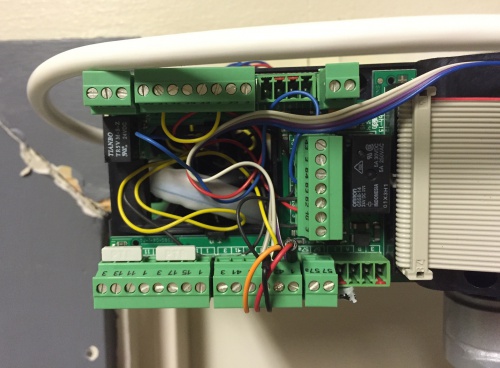
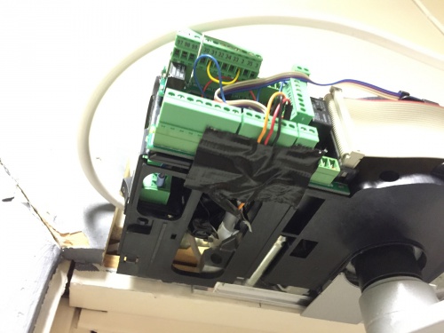
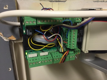
The installation process is as simple as it get. Just figure out how the existing buttons are wired and find a power&gnd lane to power everything. Luckly, the wireless module for the door was also powered by 24V so all three necessary pins were next to each other. To easy removal, I did not screw the wires into the block but just stuck them into the right terminal.
There was lots of room in the back of the unit to mount everything. This is the area where the cables from the buttons and sensors came in, so just a little re-jiggling was needed.
Working
This shows the screen of an iPhone connected to the webserver. Opening the door is as easy as just toggling the button. By making a shortcut on the home-screen directly to the toggling URL makes it even easier to engage.
