Adding SD card to WRT54GL: Difference between revisions
No edit summary |
No edit summary |
||
| (14 intermediate revisions by the same user not shown) | |||
| Line 7: | Line 7: | ||
MMC/SD cards has a SPI interface making it easy to connect to the router through the GPIO lines. There are 4 connections; CS, DI, DO and CLK. In addition to 3.3V and Ground. | MMC/SD cards has a SPI interface making it easy to connect to the router through the GPIO lines. There are 4 connections; CS, DI, DO and CLK. In addition to 3.3V and Ground. | ||
{| border="0" cellpadding="2" cellspacing="1" style="background:#ccc; float: | {| border="0" cellpadding="2" cellspacing="1" style="background:#ccc; float:left; margin:10px" | ||
|- | |- | ||
! style="background:#fff"|Pin | ! style="background:#fff"|Pin | ||
| Line 114: | Line 55: | ||
|} | |} | ||
<div style="clear: both;"></div> | |||
{| border="0" cellpadding="2" cellspacing="1" style="background:#ccc; float:left; margin:10px" | |||
|- | |||
|style="background:#fff" rowspan="8"|[[Image: SD secure digital card pinout.gif]] | |||
!style="background:#fff"|Secure Digital - SD card | |||
|- | |||
|style="background:#fff"|1. '''CS''' - Chip Select for the SD card | |||
|- | |||
|style="background:#fff"|2. '''DI''' - Data in on the SD card | |||
|- | |||
|style="background:#fff"|3. '''VSS''' - Ground is a good thing | |||
|- | |||
|style="background:#fff"|4. '''VDD''' - Power - 2.8 to 3.6V will do | |||
|- | |||
|style="background:#fff"|5. '''CLK''' - The clock we generate for the SD card | |||
|- | |||
|style="background:#fff"|6. '''VSS2''' - Another ground is also a good thing | |||
|- | |||
|style="background:#fff"|7. '''DO''' - Data out from the SD card | |||
|} | |||
{| border="0" cellpadding="2" cellspacing="1" width="300" style="background:#ccc; float:left; margin:10px" | |||
|- | |||
|style="background:#fff" rowspan="9"|[[Image: miniSD secure digital card pinout.gif]] | |||
!style="background:#fff"|Secure Digital - miniSD card | |||
|- | |||
|style="background:#fff"|1. '''CS''' - Chip Select | |||
|- | |||
|style="background:#fff"|2. '''DI''' - Data in | |||
|- | |||
|style="background:#fff"|3. '''VSS''' - Ground | |||
|- | |||
|style="background:#fff"|4. '''VDD''' - 3.3V | |||
|- | |||
|style="background:#fff"|5. '''CLK''' - Clock | |||
|- | |||
|style="background:#fff"|6. '''VSS2''' - Ground | |||
|- | |||
|style="background:#fff"|7. '''DO''' - Data out | |||
|- | |||
|style="background:#fff"|8-11. DO/RSV - Not used | |||
|} | |||
{| border="0" cellpadding="2" cellspacing="1" width="300" style="background:#ccc; float:left; margin:10px" | |||
|- | |||
|style="background:#fff" rowspan="9"|[[Image: microSD secure digital card pinout.gif]] | |||
!style="background:#fff"|Secure Digital - microSD card | |||
|- | |||
|style="background:#fff"|1. RSV - Not used | |||
|- | |||
|style="background:#fff"|2. '''CS''' - Chip Select | |||
|- | |||
|style="background:#fff"|3. '''DI''' - Data in | |||
|- | |||
|style="background:#fff"|4. '''VDD''' - 3.3V | |||
|- | |||
|style="background:#fff"|5. '''CLK''' - Clock | |||
|- | |||
|style="background:#fff"|6. '''VSS''' - Ground | |||
|- | |||
|style="background:#fff"|7. '''DO''' - Data out | |||
|- | |||
|style="background:#fff"|8. RSV - Not used | |||
|} | |||
<div style="clear: both;"></div> | |||
== Soldering GPIO points == | == Soldering GPIO points == | ||
| Line 129: | Line 137: | ||
== Soldering SD card == | == Soldering SD card == | ||
I decided to test a Apacer AP1GMCSD-R 88x 1 GB microSD card instead of a full blown regular SD card. The microSD interface is identical to its parent with the lack of the second VSS2 ground point (design for sleep function). A microSD-to-SD adapter is normally included to make it easier to read | I decided to test a Apacer AP1GMCSD-R 88x 1 GB microSD card instead of a full blown regular SD card. The microSD interface is identical to its parent with the lack of the second VSS2 ground point (design for sleep function). | ||
A microSD-to-SD adapter is also normally included to make it easier to read in a standard card reader, same goes for the miniSD card. | |||
For power and ground I used the closes to the GPIO points I could find. But there are easier spots to solder, like the serial port; 3.3V is on pin 1 and pin2 and ground on pin 9 and pin 10. | |||
[[Image: Wrt54gl sdcard points.jpg|400px]] [[Image: Wrt54gl sdcard points side.jpg|400px]] | [[Image: Wrt54gl sdcard points.jpg|400px]] [[Image: Wrt54gl sdcard points side.jpg|400px]] | ||
| Line 215: | Line 227: | ||
} | } | ||
exec /bin/busybox init | exec /bin/busybox init | ||
To install the new init script, do the following: | |||
# Save the script above as <tt>/tmp/init</tt> | # Save the script above as <tt>/tmp/init</tt> | ||
| Line 255: | Line 269: | ||
* Read&write: 3min 37sec, averaging '''117 KB/s''' | * Read&write: 3min 37sec, averaging '''117 KB/s''' | ||
[[Image: Wrt54gl sdcard overview.jpg|400px]] | |||
== References == | == References == | ||
| Line 260: | Line 276: | ||
* [http://wiki.openwrt.org/OpenWrtDocs/KamikazeConfiguration/PackagesOnExternalMediaHowTo OpenWrt PackagesOnExternalMediaHowto] | * [http://wiki.openwrt.org/OpenWrtDocs/KamikazeConfiguration/PackagesOnExternalMediaHowTo OpenWrt PackagesOnExternalMediaHowto] | ||
* [http://wiki.openwrt.org/OpenWrtDocs/Hardware/Linksys/WRT54GL OpenWrt WRT54GL] | * [http://wiki.openwrt.org/OpenWrtDocs/Hardware/Linksys/WRT54GL OpenWrt WRT54GL] | ||
* [http://www.hardwarebook.info/MicroSD HwB microSD info] | |||
* [http://www.hardwarebook.info/Secure_Digital HwB Secure Digital info] | |||
Latest revision as of 17:59, 9 June 2008
The WRT54GL is a cool little router based on Linux (GPL) and Open Source, thus allowing for extension of the core functions via software and hardware.
As the storage device is only 4 MB flash memory it's a pretty limiting factor. Fortunately, it's possible to reprogram the GPIO (General Purpose Input/Output) lines connected to the LEDs and buttons/switches.
Pin layout
MMC/SD cards has a SPI interface making it easy to connect to the router through the GPIO lines. There are 4 connections; CS, DI, DO and CLK. In addition to 3.3V and Ground.
| Pin | Direction | WRT54GL Name | SD Card Name |
|---|---|---|---|
| GPIO 0 | (Output) | Unknown | Not used |
| GPIO 1 | Output | POWER LED | Not used |
| GPIO 2 | Output | WHITE LED | DI |
| GPIO 3 | Output | AMBER LED | CLK |
| GPIO 4 | Input | FRONT BUTTON | DO |
| GPIO 5 | Output | Unknown | Not used |
| GPIO 6 | Input | Unknown | Not used |
| GPIO 7 | Output | DMZ LED | CS |

|
Secure Digital - miniSD card |
|---|---|
| 1. CS - Chip Select | |
| 2. DI - Data in | |
| 3. VSS - Ground | |
| 4. VDD - 3.3V | |
| 5. CLK - Clock | |
| 6. VSS2 - Ground | |
| 7. DO - Data out | |
| 8-11. DO/RSV - Not used |

|
Secure Digital - microSD card |
|---|---|
| 1. RSV - Not used | |
| 2. CS - Chip Select | |
| 3. DI - Data in | |
| 4. VDD - 3.3V | |
| 5. CLK - Clock | |
| 6. VSS - Ground | |
| 7. DO - Data out | |
| 8. RSV - Not used |
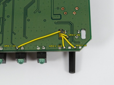
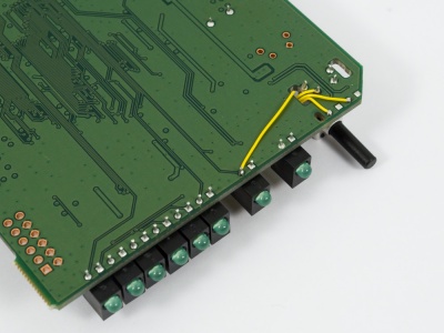
Soldering GPIO points
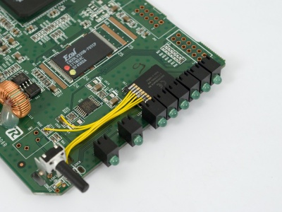
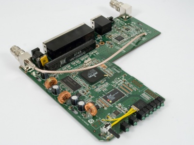
The GPIO points on the WRT54GL are all in the front hear the corner where the SES button/switch is located.
Wires installed on the underside of the PCB:
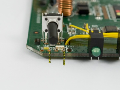
There are alternative points for GPIO 2 and GPIO 3 on the topside of the PCB, on the right side on each LED and both the VIA (orange circle) and LED pad (silver solder):
Soldering SD card
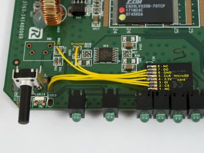
I decided to test a Apacer AP1GMCSD-R 88x 1 GB microSD card instead of a full blown regular SD card. The microSD interface is identical to its parent with the lack of the second VSS2 ground point (design for sleep function).
A microSD-to-SD adapter is also normally included to make it easier to read in a standard card reader, same goes for the miniSD card.
For power and ground I used the closes to the GPIO points I could find. But there are easier spots to solder, like the serial port; 3.3V is on pin 1 and pin2 and ground on pin 9 and pin 10.
Software
I recommend running the Kamikaze release of OpenWrt. It's more refined than White Russian, the previous released.
Once OpenWrt is installed on the unit, download and load the MMC module. There are a MMC driver in the Kamikaze package repository but it's not as good as the other optimized MMC driver available.
- Download the MMC GPIO2 v1.3.4 or new driver from the OpenWrt wiki, alternatively directly from the forum thread
- Extract the tarball, tar zxvf mmc-v1.3.4-gpio2.tgz
- Copy the module to the kernel module directory, cp mmc-v1.3.4-gpio2/mmc.o /lib/module/2.4.34/
- Set the correct GPIO mask, found by adding up all the GPIO line hex values, 0x04 + 0x08 + 0x10 + 0x80 = 0x9c, echo 09c > /proc/diag/gpiomask
- Load the module, insmod mmc
- And view the output of the kernel ring buffer, dmesg, if everything went well and there is a partition on the SD card it should end with a mmca: p1 message
[INFO] mmc_hardware_init: initializing GPIOs
[INFO] mmc_card_init: the period of a 380KHz frequency lasts 524 CPU cycles
[INFO] mmc_card_init: powering card on. sending 80 CLK
[INFO] mmc_card_init: 80 CLK sent in 43646 CPU cycles
[INFO] mmc_card_init: resetting card (CMD0)
[INFO] mmc_card_init: doing initialization loop
[INFO] mmc_card_init: card inited successfully in 2 tries (61580 CPU cycles).
[INFO] mmc_init: MMC/SD Card ID:
1b 53 4d 30 30 30 30 30 10 b1 c5 df 89 00 83 f3 [INFO] Manufacturer ID   : 1b
[INFO] OEM/Application ID: SM
[INFO] Product name      : 00000
[INFO] Product revision  : 1.0
[INFO] Product SN        : b1c5df89
[INFO] Product Date      : 2008-3
[INFO] mmc_card_config: size = 994816, hardsectsize = 512, sectors = 1989632
[WARN] mmc_init: hd_sizes=994816, hd[0].nr_sects=1989632
[INFO] mmc_card_init: set_blocklen (CMD16) succeeded !
Partition check:
 mmca: p1
Move filesystem
To make proper use of the new storage space, it makes sense to relocate the root filesystem (/) to the SD card and run the main system from there. This will leave the SquashFS on the flash chip and is only used too boot the router (before it switches over to the SD card) and for FailSafe procedures.
Linux works best when the the SD card is formatted as ext2 or ext3. Filesystems like fat or fat32 does not support things like symbolic links and nodes. Most SD cards are fat or fat32 formatted from the factory.
- Install the e2fsprogs package, ipkg install e2fsprogs
- Install the ext3 kernel module, ipkg install kmod-fs-ext3
- Format the partition, mkfs.ext3 /dev/mmc/disc0/part1
- Mount the new ext3 filesystem, mount -t ext3 /dev/mmc/disc0/part1 /mnt/
- Try to create or copy files or directories to the SD card, mkdir -p /mnt/itworks/great/
To prepare the move, create a new config in /etc/config called bootfromexternalmedia containing essential information like parition path, filesystem, and gpiomask of the SD card.
config bootfromexternalmedia
        option target   '/mnt'
        option device   '/dev/mmc/disc0/part1'
        option gpiomask '0x9c'
        option modules  'mmc jbd ext3'
        option enabled  '1'
Next, create a /sbin/init script which run after /etc/preinit and before the real /sbin/init.
Init script:
#!/bin/sh
. /etc/functions.sh
config_load "bootfromexternalmedia"
local section="cfg1"
config_get      "target"   "$section" "target"
config_get      "device"   "$section" "device"
config_get      "gpiomask" "$section" "gpiomask"
config_get      "modules"  "$section" "modules"
config_get_bool "enabled"  "$section" "enabled" '1'
[ "$enabled" -gt 0 ] && {
       [ -n "$gpiomask" ] && {
                echo "$gpiomask" > /proc/diag/gpiomask
        }
        for module in $modules; do {
                insmod $module
        }; done
        sleep 5s
        mount -o rw "$device" $target
        [ -x $target/sbin/init ] && {
                . /bin/firstboot
                pivot $target $target
        }
}
exec /bin/busybox init
To install the new init script, do the following:
- Save the script above as /tmp/init
- Make it executable, chmod a+x /tmp/init
- Remove the old init symblink, rm /sbin/init
- Move the script over, mv /tmp/init /sbin
- Verify that everything is in place and the scripts are set up properly
A final step is to copy the basic root filesystem from /rom to the SD card. It's better to start from scratch than moving the existing system over, i.e. no /sbin/init loops, etc.
- Create a new mount point, mkdir -p /tmp/root
- Link the rom filesystem to the mount point, mount -o bind /rom /tmp/root
- Copy the content, cp /tmp/root/* /mnt -a
- Flush the cache, sync
- Dismount the directories, umount /tmp/root and umount /mnt
Reboot and wait for the system to boot into the new filesystem first the first time. Since this is a new root filesystem, nothing is configured and you have to telnet in to set up the system, telnet 192.168.1.1.
The old filesystem and files can still be found via the /jffs mount.
root@OpenWrt:/www# df -h
Filesystem                Size      Used Available Use% Mounted on
none                      7.0M     40.0k      6.9M   1% /tmp
/dev/mtdblock/4           2.0M    720.0k      1.3M  35% /jffs
mini_fo:/jffs             1.2M      1.2M         0 100% /mnt
/dev/mmc/disc0/part1    955.8M     28.8M    878.5M   3% /
Performance
The performance is not essential to this system but it's OK. The card is rated 88x, meaning 150 KB/s x 88, 13.2 MB/s read speed.
The system memory is the limiting factor when transferring files to the unit via SCP, it halts for a moment several times during a transfer.
Transferring a 25.6 MB file over wired network:
- Write: 2min 47sec, averaging 158 KB/s
- Read: 1min 55 sec, averaging 220 KB/s
Copying the same file internally to itself:
- Read&write: 3min 37sec, averaging 117 KB/s

