Electric Bobby Car Hoverboard Upgrade: Difference between revisions
No edit summary |
No edit summary |
||
| (68 intermediate revisions by the same user not shown) | |||
| Line 1: | Line 1: | ||
This project puts | [[Image:bobby_car_hoverboard_upgrade_bigbobbycar.jpg|500px|right]] | ||
This project puts four 350W hoverboard motors in a Big Bobby Car toy vehicle, to give it independent four wheel drive and a top speed of 29km/h with turbo activated. All controlled by two potentiometer triggers on the steering wheel. | |||
* [[Electric Bobby Car Build]] - my version of the E-Bobby Car convesion | |||
* [[Electric Hoverboard Monorover R2 Teardown]] - overview of a Hoverboard | |||
== Specifications == | == Specifications == | ||
[[Image:Hoverboard left platform.jpg|right|400px]] | |||
* Project start: January 2019 | * Project start: January 2019 | ||
* | * Controller: 2x Hoverboard main boards - 2015 date | ||
** MCU: STM32F103 72MHz ARM Cortex-M3 core | |||
** Flasher: ST-Link V2 Programming Unit clone | ** Flasher: ST-Link V2 Programming Unit clone | ||
* Motors: 4x direct drive 3-phase brushless | * Motors: 4x direct drive 3-phase brushless electric wheel hub motors (BLDC) with hall effect sensors, 350W nom., 800W peak | ||
** Continuous Current(A): 1 to 25A | |||
* Tire type: non-pneumatic rubber tire, road pattern | * Tire type: non-pneumatic rubber tire, road pattern | ||
* Tire size: 7-inch / 170 mm | * Tire size: 7-inch / 170 mm | ||
| Line 12: | Line 19: | ||
* Charger: Lithium-ion charger 42V 2A 3-pin connector with built-in fan | * Charger: Lithium-ion charger 42V 2A 3-pin connector with built-in fan | ||
** Upgrade: External charger for anything else | ** Upgrade: External charger for anything else | ||
* Internal connectors: JST | * Internal connectors: | ||
* Vehicle base type: BIG New Bobby Car Red | ** PCB headers: JST B4B-XH-A 2.54mm pitch | ||
** Cable connectors: JST SM 4-pin and 5-pin 2.54mm pitch | |||
* Vehicle base type: BIG New Bobby-Car Red - note that it's the BIG version, easier to put your legs over the front wheel | |||
** Vehicle upgrade: Small cussion to improve seating comfort | |||
* Dimensions assembled: L57 x W30 x H39 cm | * Dimensions assembled: L57 x W30 x H39 cm | ||
* Original load-bearing: 50 kg max. | * Original load-bearing: 50 kg max. - exceeded 150% 🤭 | ||
<div id="clear"></div> | |||
== Control inputs == | |||
The hacked firmware supports a quite a few different types of control types, either partially or fully emplemented: | |||
# ADC Analog voltage input via potentiometer - safety pull-down resistors on ADC1 and ADC2 recommended, high frequency filter to smoothen out the voltage | |||
# I2C Nintendo Nunchuck official remote - I2C pull-ups required on SDA and SCL | |||
# UART Serial control via another MCU or directly via terminal | |||
# PPM Remote control via R/C radio | |||
== Overview == | |||
A rough overview of the components in the system. | |||
[[Image:bobby_car_hoverboard_upgrade_overview.png|600px]] | |||
== Schematics == | |||
* [[File:hoverboard_schematic_full_reverse.pdf]] - Full reverse engineered schematic of the classic hoverboard circuit board | |||
* [[File:hoverboard_schematic_simple_reverse.pdf]] - Simplified schematic the circuit board | |||
== Pin-out == | |||
Schematic and pin-out of the hoverboard connections, by [https://github.com/NiklasFauth/hoverboard-firmware-hack NiklasFauth]. Pulled from the [[Media:hoverboard_schematic_full_reverse.pdf|full schematic]]. | |||
[[Image:hoverboard_main_schematic.png|600px]] | |||
Illustration courtesy NiklasFauth. | |||
[[Image:hoverboard_pinouts_main_board.png|600px]] | |||
STM32F103 MCU pin-out: | |||
[[Image:hoverboard_pinouts_STM32F103.png|600px]] | |||
== Throttle filter and connection board == | |||
This is a PCB I designed to break out the ADC/UART/PPM/I2C signals to make it easier to finish the build. It has master and slave throttle splitting, where one driver board can be turned off without interfereing with the other - allows for 2x2 front/rear or 4x4 drive! | |||
It also adds filtering to the analog signals for voltage/potentiometer based throttle and pull-ups to the I2C-lanes for Nunchuck-throttle. All configurable via solder-jumpers for quick setup/change. | |||
Inspired by the [https://github.com/Jan--Henrik/hoverboard-breakout Jan Henrik break-out boards]. | |||
* [[File:bobbycar_hoverboard_throttle_breakout_schematic.pdf|Bobbycar throttle breakout schematic]] - Schematic | |||
* [http://ivc.no/bobbycar-electric/bobbycar_throttle_rev6.rar Bobbycar throttle breakout board] - PCB Gerber-files | |||
* [http://ivc.no/bobbycar-electric/bobbycar_throttle_rev6.csv Bobbycar throttle breakout BOM] - Required components | |||
[[Image:bobbycar_hoverboard_throttle_breakout_schematic.png|550px]] | |||
[[Image:bobbycar_hoverboard_throttle_breakout_pcb_top.png|450px]] | |||
[[Image:bobbycar_hoverboard_throttle_breakout_pcb_bottom.png|450px]] | |||
== Inspiration == | == Inspiration == | ||
* [https://larsm.org/allrad-e-bobby-car/ Larsm Allrad e-Bobby Car] - great write up and custom firmware fork | * [https://larsm.org/allrad-e-bobby-car/ Larsm Allrad e-Bobby Car] - great write up and custom firmware fork | ||
* [https://github.com/NiklasFauth/hoverboard-firmware-hack Niklas Fauth Hoverboard firmware hack] - original firmware | * [https://github.com/NiklasFauth/hoverboard-firmware-hack Niklas Fauth Hoverboard firmware hack] - original firmware | ||
** [https://media.ccc.de/v/gpn18-95-howto-moving-objects CCC GPN18 HowTo: Moving Objects] - great talk | |||
** [https://github.com/NiklasFauth/hoverboard-firmware-hack/wiki/Build-Instruction:-TranspOtter Build Instruction: TranspOtter] - Another build, lots of helpful pictures | |||
* [https://figch.de/index.php?nav=bobbycar Fisch's detailed build guide] - great documentation of the assembly | |||
** [https://figch.de/index.php?nav=bobbycar_trailer Fisch's trailer build] - trailer for the Bobby Car | |||
* [https://github.com/Jan--Henrik/hoverboard-breakout Jan Henrik breakout boards] - PCBs for easy connection to serial and Nunchuck | |||
* [https://drewspewsmuse.blogspot.com/2016/06/how-i-hacked-self-balancing-scooter.html Drew's How I hacked the Self Balancing Scooter] | |||
* [https://github.com/cloidnerux/hoverboard-firmware-hack cloidnerux AT32F403RCT6 firmware] - for newer mainboards with the AT32F403RCT6 MCU] | |||
Latest revision as of 08:10, 29 May 2020
This project puts four 350W hoverboard motors in a Big Bobby Car toy vehicle, to give it independent four wheel drive and a top speed of 29km/h with turbo activated. All controlled by two potentiometer triggers on the steering wheel.
- Electric Bobby Car Build - my version of the E-Bobby Car convesion
- Electric Hoverboard Monorover R2 Teardown - overview of a Hoverboard
Specifications
- Project start: January 2019
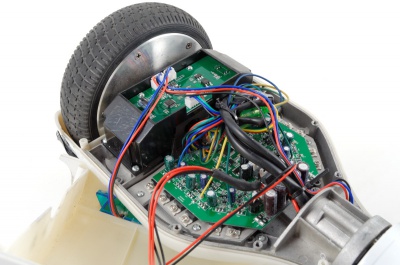
- Controller: 2x Hoverboard main boards - 2015 date
- MCU: STM32F103 72MHz ARM Cortex-M3 core
- Flasher: ST-Link V2 Programming Unit clone
- Motors: 4x direct drive 3-phase brushless electric wheel hub motors (BLDC) with hall effect sensors, 350W nom., 800W peak
- Continuous Current(A): 1 to 25A
- Tire type: non-pneumatic rubber tire, road pattern
- Tire size: 7-inch / 170 mm
- Battery: Lithium-ion rechargeable 18650-cells, 10S2P 36V 4400mAh 158.4Wh pack with XT60 connector
- Upgrade: Controller can handle 13S (48V), 12S battery upgrade easiest
- Charger: Lithium-ion charger 42V 2A 3-pin connector with built-in fan
- Upgrade: External charger for anything else
- Internal connectors:
- PCB headers: JST B4B-XH-A 2.54mm pitch
- Cable connectors: JST SM 4-pin and 5-pin 2.54mm pitch
- Vehicle base type: BIG New Bobby-Car Red - note that it's the BIG version, easier to put your legs over the front wheel
- Vehicle upgrade: Small cussion to improve seating comfort
- Dimensions assembled: L57 x W30 x H39 cm
- Original load-bearing: 50 kg max. - exceeded 150% 🤭
Control inputs
The hacked firmware supports a quite a few different types of control types, either partially or fully emplemented:
- ADC Analog voltage input via potentiometer - safety pull-down resistors on ADC1 and ADC2 recommended, high frequency filter to smoothen out the voltage
- I2C Nintendo Nunchuck official remote - I2C pull-ups required on SDA and SCL
- UART Serial control via another MCU or directly via terminal
- PPM Remote control via R/C radio
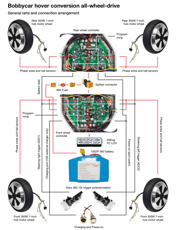
Overview
A rough overview of the components in the system.
Schematics
- File:Hoverboard schematic full reverse.pdf - Full reverse engineered schematic of the classic hoverboard circuit board
- File:Hoverboard schematic simple reverse.pdf - Simplified schematic the circuit board
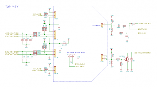
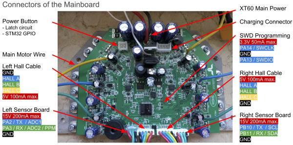
Pin-out
Schematic and pin-out of the hoverboard connections, by NiklasFauth. Pulled from the full schematic.
Illustration courtesy NiklasFauth.
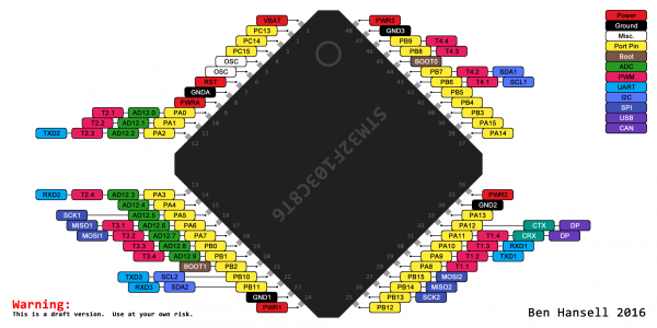
STM32F103 MCU pin-out:
Throttle filter and connection board
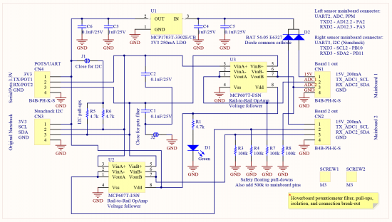
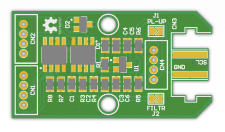
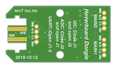
This is a PCB I designed to break out the ADC/UART/PPM/I2C signals to make it easier to finish the build. It has master and slave throttle splitting, where one driver board can be turned off without interfereing with the other - allows for 2x2 front/rear or 4x4 drive!
It also adds filtering to the analog signals for voltage/potentiometer based throttle and pull-ups to the I2C-lanes for Nunchuck-throttle. All configurable via solder-jumpers for quick setup/change.
Inspired by the Jan Henrik break-out boards.
- File:Bobbycar hoverboard throttle breakout schematic.pdf - Schematic
- Bobbycar throttle breakout board - PCB Gerber-files
- Bobbycar throttle breakout BOM - Required components
Inspiration
- Larsm Allrad e-Bobby Car - great write up and custom firmware fork
- Niklas Fauth Hoverboard firmware hack - original firmware
- CCC GPN18 HowTo: Moving Objects - great talk
- Build Instruction: TranspOtter - Another build, lots of helpful pictures
- Fisch's detailed build guide - great documentation of the assembly
- Fisch's trailer build - trailer for the Bobby Car
- Jan Henrik breakout boards - PCBs for easy connection to serial and Nunchuck
- Drew's How I hacked the Self Balancing Scooter
- cloidnerux AT32F403RCT6 firmware - for newer mainboards with the AT32F403RCT6 MCU]
