MakerBot Replicator 1 Upgrades and Repairs: Difference between revisions
No edit summary |
|||
| (87 intermediate revisions by the same user not shown) | |||
| Line 4: | Line 4: | ||
[[MakerBot Replicator 1 Firmware Upgrade]] | [[MakerBot Replicator 1 Firmware Upgrade]] | ||
Need repair service? I can offer most fixes of the MightyBoard and related electronics. Contact me at http://beta.ivancover.com/blog/wp-content/uploads/2006/09/ivc-email.png for a quote. | |||
== General Upgrades == | == General Upgrades == | ||
| Line 14: | Line 16: | ||
# Replace the MK8 delrin plungers with a [http://www.thingiverse.com/thing:28241 spring-loaded one]. There's some screws and springs needed, but the filament loading should be much more smooth and it's easier to clean the feed gear. | # Replace the MK8 delrin plungers with a [http://www.thingiverse.com/thing:28241 spring-loaded one]. There's some screws and springs needed, but the filament loading should be much more smooth and it's easier to clean the feed gear. | ||
# Change the rubber feet. Print out a [http://www.thingiverse.com/thing:24183 set of round feet] and apply four adhesive non-skid gripper pads to the bottom to minimize vibrations and noise. | # Change the rubber feet. Print out a [http://www.thingiverse.com/thing:24183 set of round feet] and apply four adhesive non-skid gripper pads to the bottom to minimize vibrations and noise. | ||
# Upgrade to Orion fans. The stock fans can wear out and is a bit noise. | # Upgrade to Orion OD4010-24HB 40x40x10mm 24V fans, all three. Some soldering required on the extruders. The stock fans can wear out and is a bit noise. | ||
# Add a glass plate on top of the aluminum platform. This makes sure the platform is absolutely level and there's no need to use kapton tape anymore. A [http://www.thingiverse.com/thing:36651 group on Thingiverse] is selling remade plates. | # Add a glass plate on top of the aluminum platform. This makes sure the platform is absolutely level and there's no need to use kapton tape anymore. A [http://www.thingiverse.com/thing:36651 group on Thingiverse] is selling remade plates. | ||
# Upgrade to aluminum heated platform arms - the plastic arms that hold the platform in place and connected to the Z axis. Not really needed if the prints generally are fine, but it might help minimize vibrations/oscillations as the heads move. | # Upgrade to aluminum heated platform arms - the plastic arms that hold the platform in place and connected to the Z axis. Not really needed if the prints generally are fine, but it might help minimize vibrations/oscillations as the heads move. | ||
| Line 21: | Line 23: | ||
The MakerBot Mightyboard Rev. E board had quite a few flaws, but all manageable and fixable [http://coolate.com/blog/blog/2015/02/23/its-alive-makerbot-replicator-repaired/], ordered from important to less important: | The MakerBot Mightyboard Rev. E board had quite a few flaws, but all manageable and fixable [http://coolate.com/blog/blog/2015/02/23/its-alive-makerbot-replicator-repaired/], ordered from important to less important: | ||
# Replaced the overloaded LM1084 5V regulator with OKI-78SR-5/1.5-W36-C or R-78E5.0-0.5 - linear regulation from 24V to 5V | # Replaced the overloaded LM1084 5V regulator with OKI-78SR-5/1.5-W36-C (tested myself and works great after 2 years) or R-78E5.0-0.5 [https://groups.google.com/d/msg/makerbot-users/rf1nNwstpNs/_D9MogNUAwAJ] - linear regulation from 24V to 5V is always tricky and there is a problem with spikes using Tantalum capacitors on the stepper drivers, fixed using new regulators | ||
# Cut the 24V trace to the 3.3V regulator and connect 5V to the regulator instead - MBI already implemented this budge wire | # Cut the 24V trace to the 3.3V regulator and connect 5V to the regulator instead - MBI already implemented this budge wire | ||
# Disable the unimplemented safety cutoff circuitry - MBI already soldered pin 4 and 5, bypassing the circuitry on both the EX0/EX1 outputs | # Disable the unimplemented safety cutoff circuitry - MBI already soldered pin 4 and 5, bypassing the circuitry on both the EX0/EX1 outputs | ||
# Add in-line a Schottky 30V 100mA diode on the 5V trace to the stepper drivers to prevent 24V back-feed if one driver fails | |||
# Solder a fast reverse protection diode on the power input to ground to prevent polarity issues, it will trigger the crowbar overload protection in the power supply [https://groups.google.com/d/msg/makerbot/Qpzv6f8wJPs/wY8UgcCmx4QJ] | |||
# On the end-stop cables, remove the white 5V wire to prevent a short in the cable to overload the 5V regulator | |||
# Switch the stepper drivers to from BotStep17 A4982 to FlashForge A4988 BotSteps | # Switch the stepper drivers to from BotStep17 A4982 to FlashForge A4988 BotSteps | ||
# Upgrade the 24V power supply to a more stable and beefier | # Upgrade the 24V power supply to a more stable and beefier 350W 24V 14.6A unit | ||
== Mainboard replacements == | == Mainboard replacements == | ||
[[Image:MakerBot Replicator Mightyboard RevE.jpg|300px|right]] | [[Image:MakerBot Replicator Mightyboard RevE.jpg|300px|right]] | ||
[[Image:MakerBot Replicator Mightyboard RevE Schematic.png|300px|right]] | [[Image:MakerBot Replicator Mightyboard RevE Schematic.png|300px|right]] | ||
[[Image:MakerBot Replicator Mightyboard RevE Board layout.png|300px|right]] | |||
The mainboard on the Replicator 1 is known as motherboard version 4.0+ (Gen4 electronics), often referred to as MBv40 or MB40. | |||
* | * [http://www.thingiverse.com/thing:16058 MakerBot MightyBoard Rev. E] [http://ivc.no/makerbot/MakerBot_MightyBoard_RevE.zip local backup] | ||
* | |||
* | These are the required chips in order to work with the official MakerBot Replicator 1 firmware: | ||
* | |||
* ATMEGA1280-16AU MCU - main code | |||
* ATMEGA8U2-MU MCU - serial bridge, USB-to-serial | |||
* MAX6675ISA+ Thermocouple amplifier | |||
* MCP4018T-502E/LT Digital POT 5K for BotStep | |||
If you can not repair the board by hand, consider getting these replacements/clones, price ranging from 99USD to 185USD: | If you can not repair the board by hand, consider getting these replacements/clones, price ranging from 99USD to 185USD: | ||
# MakerBot Mightyboard Rev. E - hard to get by in 2016, MBI says they are all sold out off stock [Ben] | # [http://www.thingiverse.com/thing:16058 MakerBot Mightyboard Rev. E] - hard to get by in 2016, MBI says they are all sold out off stock [Ben] | ||
# [http://store.mbot3d.com/motherboard-mightyboard-24v/ MBot Cube Plywood Mightyboard 24V] - ATmega1280, external 5V regulator fix | # [http://store.mbot3d.com/motherboard-mightyboard-24v/ MBot Cube Plywood Mightyboard 24V] - ATmega1280, external 5V regulator fix | ||
# [http://www.3d-printshop.biz/MightyBoard FlashForge Creator 1/2/X] - ATmega1280, fixed 5V regulator ('''recommended''') | # [http://www.3d-printshop.biz/MightyBoard FlashForge Creator 1/2/X] - ATmega1280, fixed 5V regulator ('''recommended''') | ||
| Line 54: | Line 64: | ||
Note that the official MakerBot firmware only works on ATmega1280 MCUs. Take a look at [http://jettyfirmware.yolasite.com/resources/release/firmware.xml the Sailfish firmware library] for details about other compatible boards. | Note that the official MakerBot firmware only works on ATmega1280 MCUs. Take a look at [http://jettyfirmware.yolasite.com/resources/release/firmware.xml the Sailfish firmware library] for details about other compatible boards. | ||
On new boards/clones, some of the connectors are different. These are the right models to get: | |||
* Stepper motor connector (1x): Molex 0026481045 VERT B/A HDR 4P TIN FRICTION LOCK (or 0416710003 for gold plating) | |||
* Power input connector (1x): Kycon KPJX-4S-S 4P JACK SKT SHIELDED SNAP AND LOCK | |||
* Terminal blocks, 2-pin (3-4x): Phoenix Contact Fixed 1729128 Terminal Block 2P 5.08mm 90DEG | |||
* Terminal blocks, 4-pin (3x): Phoenix Contact 1729144 Fixed Terminal Block 4P 5.08mm 90DEG | |||
<html><div style="clear:both"></div></html> | |||
== Stepper driver replacement == | == Stepper driver replacement == | ||
[[Image:MakerBot Replicator BotStep17.jpg|300px|right]] | [[Image:MakerBot Replicator BotStep17.jpg|300px|right]] | ||
[[Image:MakerBot Replicator MightyStep17.jpg|300px|right]] | |||
[[Image:MakerBot Replicator BotStep17 schematic.png|300px|right]] | [[Image:MakerBot Replicator BotStep17 schematic.png|300px|right]] | ||
* [http://store.ivc.no/product/makerbot-mightystep17 MightyStep17 Stepper Driver] - My re-designed and improved A4982 driver, fully MakerBot BotStep17 compatible | |||
* [[MakerBot Replicator 1 Adapting A4988 Replacement Driver]] | |||
The official MightyBoard comes with [http://www.thingiverse.com/thing:16059 BotStep17 Rev.E driver boards], designed by Harry Mulliken. It is based on the Allegro A4982 (not A4928 misnomer) motor driver and interface chip, in QFN package for better heat dissipation. | The official MightyBoard comes with [http://www.thingiverse.com/thing:16059 BotStep17 Rev.E driver boards], designed by Harry Mulliken. It is based on the Allegro A4982 (not A4928 misnomer) motor driver and interface chip, in QFN package for better heat dissipation. | ||
* [ | * The A4982 and A4988 can handle max. 2A output current per coil (bipolar motor has two coils) with sufficient active cooling [https://www.pololu.com/product/1182], but a normal driver as-is is only designed to handle approx. 1A per coil | ||
Setting up A4988 boards: | |||
* The Vreg signal used for setting the motor current is replaced with a MS3 (Microstep 3) signal pin, either remove the pin or cut the trace to Vreg on the Mightyboard and solder the new MS3 signal to 5V to enable 1/16 steps | |||
* Turn the trimpot to adjust the motor current limit (this replaces the Vreg functionality previously done digitally by the Makerbot firmware), a circled via on the bottom side of the board is Vref to calculate the current limit | |||
* Adjust the current limit by turning the trimpot (on A4988 boards) until the equation Vref/(8xRsense) matches approx. 830mA | |||
* Measure Vref by putting the positive prove on top of the trimpot and the negative on a common ground point | |||
** Polulu: 0.35V/(8x0.05 Ohm) = 0.875mA | |||
** Geeetech: 1.34V/(8x0.200 Ohm) = 0.8375mA | |||
Compatible boards: | |||
* [http://www.thingiverse.com/thing:16059/ MakerBot BotStep17 Rev.E] - Official Thingiverse files (schematic, BOM, layout) - [http://ivc.no/makerbot/MakerBot_BotStep17_REVE-official-thingiverse.zip local backup] | |||
** Original part, 0.270 Ohm sense resistors | |||
** Direct drop-in replacement | |||
* [http://store.ivc.no/product/makerbot-mightystep17 MightyStep17 A4982 Stepper Driver] | |||
** Fully MakerBot BotStep17 compatible | |||
* [https://github.com/Hoektronics/Shukongji/tree/master/electronics/hoekdrive17 HoekDrive17 compatible driver] | |||
** Direct drop-in replacement | |||
** Hard to get hold of, sold out | |||
* [https://www.pololu.com/product/1182 Pololu A4988 Stepper Motor Driver Carrier] - different chip but compatible | |||
** Not direct drop-in, pin header is soldered the other way around | |||
** Current Limit Imax = Vref/(8x0.05Ohm) | |||
* [http://www.geeetech.com/wiki/index.php/StepStick_A4988_Stepper_Driver_Module Geeetech A4988] | |||
** Not direct drop-in, pin header is soldered the other way around | |||
** Sense resistor is 0.200 Ohm | |||
BotStep17 Specification from Thingiverse page: | BotStep17 Specification from Thingiverse page: | ||
* Controller chip: Allegro A4982 | * Controller chip: [http://ivc.no/makerbot/A4982-Datasheet.pdf Allegro A4982] | ||
* Max. Motor Voltage: VBB 28V | * Max. Motor Voltage: VBB 28V | ||
* Max. Logic Voltage: VDD 5.5V | * Max. Logic Voltage: VDD 5.5V | ||
* Max. Power Dissipation (no heatsink): 2. | * Max. Power Dissipation (no heatsink): 2.0W | ||
* Default Vref voltage: VDD x 0.267 +- 2% | * Default Vref voltage: VDD x 0.267 +- 2% | ||
* Default | * Default motor current: Vref/2.16 +-10% | ||
* Rosc GND (mixed decay mode) | * Rosc set to GND (mixed decay mode) | ||
* Step resolution: 1/1, 1/2, 1/4, 1/16 - MakerBot firmware uses 1/16 steps, hard-wired on the Mightyboard | |||
Fixed by internal resistors 33K to VDD, 12K to GND, may be changed on pin Vreg. | |||
* Imax = Vref/(8x0.270 Ohm) - the sense resistor will change between MakerBot A4982 (0.270 Ohm), Geeetch A4988 (0.200 Ohm) and Pololu A488 (0.05 Ohm), check the board for confirmation | |||
** Fixed by internal 0 Ohm resistor | |||
* Makerbot firmware A4982 Vref defaults: | |||
** The MCP4018T-502E/LT digipots value is set to 118 for X, Y, A and B which gives Vref 1.75V (810mA max.), and 40 for Z which gives 0.60V (278mA max.). | |||
Microstep Resolution Truth Table: | Microstep Resolution Truth Table: | ||
MS1 MS2 Microstep Resolution Excitation Mode | |||
L L Full Step 2 Phase | |||
H L Half Step 1-2 Phase | |||
L H Quarter Step W1-2 Phase | |||
H H Sixteenth Step 4W1-2 Phase | |||
In an event that the BotStep burns out, to prevent 24V from back-feeding into the 5V rail, consider putting a Schottky-diode on the 5V rail. Either by cutting the trace or replacing the 5V pin on the Botstep with a diode [https://groups.google.com/d/msg/makerbot/IOhw-msylf4/peAFXgHvvv0J]. Not necessarily required. | |||
== LCD interface == | == LCD interface == | ||
[[Image:MakerBot Replicator LCD interface.jpg| | [[Image:MakerBot Replicator LCD interface.jpg|300px|right]] | ||
[[Image:MakerBot Replicator LCD interface schematic.png| | [[Image:MakerBot Replicator LCD interface back.jpg|300px|right]] | ||
[[Image:MakerBot Replicator LCD interface schematic.png|300px|right]] | |||
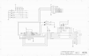
The LCD Interface Rev. B provides a display and buttons to control the 3D-printer directly. Connects to the Mightyboard via a 26-pin ribbon cable. | The LCD Interface Rev. B provides a display and buttons to control the 3D-printer directly. Connects to the Mightyboard via a 26-pin ribbon cable. | ||
* [http://www.thingiverse.com/thing:16067 Download Makerbot LCD Interface Rev. B] [http://ivc.no/makerbot/MakerBot_Replicator_Interface_Board_REVB.zip local backup] | * [http://www.thingiverse.com/thing:16067 Download Makerbot LCD Interface Rev. B] [http://ivc.no/makerbot/MakerBot_Replicator_Interface_Board_REVB.zip local backup] | ||
The board is fairly simple but has the LCD segment drivers directly integrated on the board, which makes repairing the LCD drivers very hard. | |||
* 5 push-buttons with 5v pull-up | |||
* New Haven ACM2004A FSW FGBW 4x20 character back-lite 5V LCD display | |||
** New Haven ST7066U Dot Matrix LCD Controller/Driver | |||
** AIP31063 Segment Drivers | |||
* HEF4094B 8-stage serial shift register for the LCD driver | |||
* SD Card Slot, Push In/Push Out, Reverse | |||
* SN74AHC125D quadruple bus buffer gates for 3.3v levels for the SD card slot | |||
<html><div style="clear:both"></div></html> | <html><div style="clear:both"></div></html> | ||
== Heater board == | == Heater board == | ||
[[Image:MakerBot Replicator header board.jpg| | [[Image:MakerBot Replicator header board.jpg|300px|right]] | ||
[[Image:MakerBot Replicator header board schematic.png| | [[Image:MakerBot Replicator header board circuit.jpg|300px|right]] | ||
[[Image:MakerBot Replicator header board schematic.png|300px|right]] | |||
[[Image:MakerBot Replicator header board layout.png|300px|right]] | |||
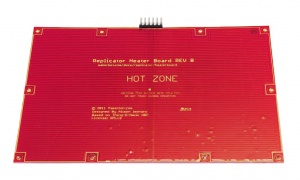
The hated build platform is a PCB board and aluminum sandwich with a 6-pin connector. | The hated build platform is a PCB board and aluminum sandwich with a 6-pin connector. | ||
* [http://www.thingiverse.com/thing:16061 Download Makerbot Heater Board Rev. B] [http://ivc.no/makerbot/MakerBot_Replicator_Heater_Board_REVB.zip local backup] | * [http://www.thingiverse.com/thing:16061 Download Makerbot Heater Board Rev. B] [http://ivc.no/makerbot/MakerBot_Replicator_Heater_Board_REVB.zip local backup] | ||
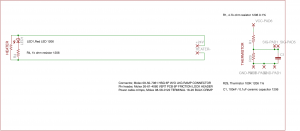
It uses a plain maze of copper traces as heater elements. Powered by 24V power and measured by a thermistor on the other side. | |||
* Header element resistance 3.9 Ohm, at 24V makes 6.2A or 148W | |||
* Thermistor 100K 1206 1%, most probable the NTHS1206N01N1003FE, B value 3964 K | |||
<html><div style="clear:both"></div></html> | |||
== Heated build platform connector replacement == | |||
[[Image:MakerBot_HBP_connector.jpg|300px|right]] | |||
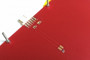
The connector on the heated build platform can sometimes be misaligned and cause a connection with bad contact, leading to resistance and thermal heat production. Replacing the connector and header is relatively simple with a plier and soldering iron. | |||
* Connector (1x): Molex 09-50-7061 HSG 6P W/O LKG RAMP CONNECTOR | |||
* Pin header (1x) - better: Molex 26-61-4060 VERT PCB 6P FRICTION LOCK HEADER Gold plated | |||
* Pin header (1x) - same as original: Molex 41671-0005 3.96mm BRKWY HDR 6P Gold plated | |||
* Power cable crimps (2-6x): Molex 08-58-0122 TERMINAL 18-20 BULK CRIMP Gold plated | |||
Pin-out: | |||
# SIG - Thermistor voltage - White | |||
# GND - Common ground - Green | |||
# GND - Common ground - Yellow - Note: can be swapped with green GND, makes no difference | |||
# 5V - Supply power - Blue | |||
# +24V - Power positive - Black | |||
# HEAT- - Power negative - Red - Note: can be swapped with +24V, makes no difference, used to heat copper | |||
A better solution, is to by-pass the Mightyboard entirely and wire the 24V from the power supply directly to the HBP by soldering to them to the traces. Alternatively, parallel the load from the power supply by using the normal power in connector and also use the screw terminals on the "CS-FAN" connector to supply 24V to the board. | |||
<html><div style="clear:both"></div></html> | <html><div style="clear:both"></div></html> | ||
== | == Mechanical end-stops == | ||
[[Image: | [[Image:MakerBot_end-stop.jpg|300px|right]] | ||
[[Image:MakerBot_end-stop_board.png|300px|right]] | |||
[[Image:MakerBot_end-stop_schematic.png|300px|right]] | |||
There are four end-stops used on the Replicator 1; x-max, y-max and z-min. | |||
* [http://www.thingiverse.com/thing:4971 MakerBot Replicator 1 Mechanical End-stop v1.2] - [http://ivc.no/makerbot/Mechanical_Endstop_v12.zip local backup] | |||
To prevent over-loading the 5V regulator in an event that the cable wears out and 5V shorts to GND, remove and isolate the white 5V pin from the locking-connector, or add a 1k resistor in series to limit the current [https://groups.google.com/forum/#!topic/makerbot/DXPdaALvlgI]. This pin is used to pull-up the signal pin and light up the red-LED on the end-stop board, but the former is done in the main microcontroller. You can test if the cable is shorted by checking the continuity between the white and any of the two black wires, it should be open. | |||
<html><div style="clear:both"></div></html> | |||
== Power supply replacement == | |||
[[Image:MakerBot_power_supply.jpg|300px|right]] | |||
The Replicator 1 came with a good 24V 9.2V PSU. A replacement should be 24V and 10A or better, the heated build platform by itself uses 150W of power. | |||
Original: | |||
* [http://ivc.no/makerbot/gs220-spec-767464.pdf Mean Well GS220A24-R7B 221W 24V 9.2A desktop AC adapter] - UL/TUV certified | |||
** Power plug: KYCON KPPX-4P DIN 4-pin with lock type, rated for 20V 7.5A | |||
Replacement: | |||
* | * Meanwell SE-350-24 350W 24V 14.6A switching power supply [https://groups.google.com/d/msg/makerbot-users/rf1nNwstpNs/BqelDYnsDAAJ] | ||
* | ** Power inlet socket: Schurter 6100.3300 AC Power Entry Modules PNL SCREW-ON .250 QC | ||
* | |||
<html><div style="clear:both"></div></html> | <html><div style="clear:both"></div></html> | ||
== Belt replacements == | == Belt replacements == | ||
[[Image:MakerBot Replicator belt.jpg| | [[Image:MakerBot Replicator belt.jpg|300px|right]] | ||
The Replicator 1 has GT2 belts from both SDP/SI and Gates. SDP/SI actually puts the part number on the belt, while Gates does not put the part numbers on - you have to infer it. | The Replicator 1 has GT2 belts from both SDP/SI and Gates. SDP/SI actually puts the part number on the belt, while Gates does not put the part numbers on - you have to infer it. | ||
Recommended to get them via the [http://www.sdp-si.com/products/belts/gt2.htm SDI SI store]. | Recommended to get them via the [http://www.sdp-si.com/products/belts/gt2.htm SDI SI store]. | ||
* Y axis, left hand side: SDP A 6R51M293060 Made in Japan | * '''Y axis, left hand side''': SDP A 6R51M293060 Made in Japan | ||
** "2MR-586-06" and "A 6R51M293060" is the inferred part number you need to look for | ** "2MR-586-06" and "A 6R51M293060" is the inferred part number you need to look for | ||
** GT2 -> 2mm pitch; "293 grooves; 586 mm length; 6.0 mm wide | ** GT2 -> 2mm pitch; "293 grooves; 586 mm length; 6.0 mm wide | ||
* Y axis, right hand side: Gates GT 2MR293 Made in Japan | * ''''Y axis, right hand side''': Gates GT 2MR293 Made in Japan | ||
** "2MR-586-06" and "A 6R51M293060" is the inferred part number you need to look for | ** "2MR-586-06" and "A 6R51M293060" is the inferred part number you need to look for | ||
** 2MR -> GT2 -> 2mm pitch; 293 grooves; 586 mm length; 6.0 mm wide | ** 2MR -> GT2 -> 2mm pitch; 293 grooves; 586 mm length; 6.0 mm wide | ||
* X axis: Gates GT 2MR424 | * '''X axis, extruder carriage''': Gates GT 2MR424 | ||
** "2MR-848-06" and "A 6R51M424060" is the inferred part number you need to look for | ** "2MR-848-06" and "A 6R51M424060" is the inferred part number you need to look for | ||
** 2MR -> GT2 -> 2mm pitch; 424 grooves; 848 mm length; 6.0 mm wide | ** 2MR -> GT2 -> 2mm pitch; 424 grooves; 848 mm length; 6.0 mm wide | ||
* Y axis belt on back stepper motor, small: Gates PGGT 2MR-166 | * '''Y axis, belt on back stepper motor, small''': Gates PGGT 2MR-166 | ||
** "2MR-166-06" and "A 6R51M083060" is the inferred part number you need to look for | ** "2MR-166-06" and "A 6R51M083060" is the inferred part number you need to look for | ||
** 2MR -> GT2 -> 2mm pitch; 83 grooves; 166 mm length 6.0 mm wide | ** 2MR -> GT2 -> 2mm pitch; 83 grooves; 166 mm length 6.0 mm wide | ||
| Line 145: | Line 260: | ||
* [https://groups.google.com/forum/?fromgroups=#!topic/makerbot/jT184sCEItw Replicator Top 10 upgrades thread] | * [https://groups.google.com/forum/?fromgroups=#!topic/makerbot/jT184sCEItw Replicator Top 10 upgrades thread] | ||
* [http://www.thingiverse.com/thing:35857 Replicator Upgrade Thingiverse List] | * [http://www.thingiverse.com/thing:35857 Replicator Upgrade Thingiverse List] | ||
* [https://groups.google.com/forum/#!topic/makerbot/5n4HwWyazlE MightyBoard Failure Analysis by Gary] | |||
* [http://coolate.com/blog/blog/2015/02/23/its-alive-makerbot-replicator-repaired/ It’s Alive! Makerbot replicator repaired!] | * [http://coolate.com/blog/blog/2015/02/23/its-alive-makerbot-replicator-repaired/ It’s Alive! Makerbot replicator repaired!] | ||
* [https://www.reddit.com/r/3Dprinting/comments/3rns41/shorted_my_3d_printer_mightyboard_could_i_replace/ Shorted my 3d printer Mightyboard] | * [https://www.reddit.com/r/3Dprinting/comments/3rns41/shorted_my_3d_printer_mightyboard_could_i_replace/ Shorted my 3d printer Mightyboard] | ||
Latest revision as of 18:17, 6 September 2017
This is a quick list of great upgrades to improve the printing quality of the MakerBot Replicator 1.
MakerBot Replicator 1 Firmware Upgrade
Need repair service? I can offer most fixes of the MightyBoard and related electronics. Contact me at  for a quote.
General Upgrades
Below is a list of some good tips for improving printing performance and accuracy.
- First major upgrade should be side panels and maybe a hood. You want to control the air flow in the print chamber and help keep the chamber temperature stable. This will greatly minimize, or maybe eliminate, peeling/curling of ABS prints. A cheap method is to just use a few large paper sheets to cover up the sides including the top.
- Flash the Sailfish Firmware. The standard firmware is fine, but the Sailfish firmware, and the Sailfish team, are more responsive and consistent. The end result is the prints seem to be much better with less fuss. Your mileage may vary though.
- Proper nozzle gap. Once you figure out the leveling thing, you then have to get the proper gap between the nozzle and the plate. The bead should be flatter than rounder. Too flat and the nozzle will clog. Too round and the parts won't stick. Print a one layer thick item, then measure it and make sure it is within 0.02mm(ish) of the target layer height (0.1-0.3mm)
- Next major tool is leveling. Get a dial gauge indicator and print a mounting bracket. This will help get your platform level much faster. Also, level while the platform is heated.
- Replace the MK8 delrin plungers with a spring-loaded one. There's some screws and springs needed, but the filament loading should be much more smooth and it's easier to clean the feed gear.
- Change the rubber feet. Print out a set of round feet and apply four adhesive non-skid gripper pads to the bottom to minimize vibrations and noise.
- Upgrade to Orion OD4010-24HB 40x40x10mm 24V fans, all three. Some soldering required on the extruders. The stock fans can wear out and is a bit noise.
- Add a glass plate on top of the aluminum platform. This makes sure the platform is absolutely level and there's no need to use kapton tape anymore. A group on Thingiverse is selling remade plates.
- Upgrade to aluminum heated platform arms - the plastic arms that hold the platform in place and connected to the Z axis. Not really needed if the prints generally are fine, but it might help minimize vibrations/oscillations as the heads move.
Mainboard fixes
The MakerBot Mightyboard Rev. E board had quite a few flaws, but all manageable and fixable [1], ordered from important to less important:
- Replaced the overloaded LM1084 5V regulator with OKI-78SR-5/1.5-W36-C (tested myself and works great after 2 years) or R-78E5.0-0.5 [2] - linear regulation from 24V to 5V is always tricky and there is a problem with spikes using Tantalum capacitors on the stepper drivers, fixed using new regulators
- Cut the 24V trace to the 3.3V regulator and connect 5V to the regulator instead - MBI already implemented this budge wire
- Disable the unimplemented safety cutoff circuitry - MBI already soldered pin 4 and 5, bypassing the circuitry on both the EX0/EX1 outputs
- Add in-line a Schottky 30V 100mA diode on the 5V trace to the stepper drivers to prevent 24V back-feed if one driver fails
- Solder a fast reverse protection diode on the power input to ground to prevent polarity issues, it will trigger the crowbar overload protection in the power supply [3]
- On the end-stop cables, remove the white 5V wire to prevent a short in the cable to overload the 5V regulator
- Switch the stepper drivers to from BotStep17 A4982 to FlashForge A4988 BotSteps
- Upgrade the 24V power supply to a more stable and beefier 350W 24V 14.6A unit
Mainboard replacements
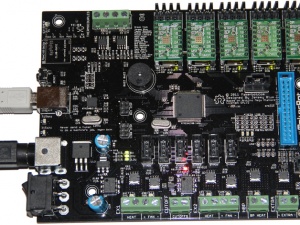
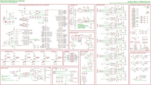
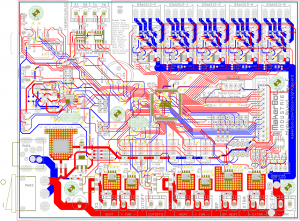
The mainboard on the Replicator 1 is known as motherboard version 4.0+ (Gen4 electronics), often referred to as MBv40 or MB40.
These are the required chips in order to work with the official MakerBot Replicator 1 firmware:
- ATMEGA1280-16AU MCU - main code
- ATMEGA8U2-MU MCU - serial bridge, USB-to-serial
- MAX6675ISA+ Thermocouple amplifier
- MCP4018T-502E/LT Digital POT 5K for BotStep
If you can not repair the board by hand, consider getting these replacements/clones, price ranging from 99USD to 185USD:
- MakerBot Mightyboard Rev. E - hard to get by in 2016, MBI says they are all sold out off stock [Ben]
- MBot Cube Plywood Mightyboard 24V - ATmega1280, external 5V regulator fix
- FlashForge Creator 1/2/X - ATmega1280, fixed 5V regulator (recommended)
- Core-XY MightyBoard Rev. E - ATmega1280, but a ATmega2560 also exists
- Geeetech Mightyboard Rev. G - ATmega1280, fixed 5V regulator, MAX6675, SD card slot, released May 2015, require adjustments to work with MakerWare
- Geeetech Mightyboard Rev. E - Bad revision, ATmega1280, released October 2014 which is direct clone and has bad regulator
- Wanhao Duplicator 4 Mightyboard Rev. A - ATmega1280, fixed 5V regulator, side mounted 24V connector, no RGB LED driver, might have crystal problems
- FlashForge Creator Pro Mightyboard - ATmega2560, side slide-connectors
New and unique adaptions:
- CloneBoard Mini - recreated board, ATmega2560
Note that the official MakerBot firmware only works on ATmega1280 MCUs. Take a look at the Sailfish firmware library for details about other compatible boards.
On new boards/clones, some of the connectors are different. These are the right models to get:
- Stepper motor connector (1x): Molex 0026481045 VERT B/A HDR 4P TIN FRICTION LOCK (or 0416710003 for gold plating)
- Power input connector (1x): Kycon KPJX-4S-S 4P JACK SKT SHIELDED SNAP AND LOCK
- Terminal blocks, 2-pin (3-4x): Phoenix Contact Fixed 1729128 Terminal Block 2P 5.08mm 90DEG
- Terminal blocks, 4-pin (3x): Phoenix Contact 1729144 Fixed Terminal Block 4P 5.08mm 90DEG
Stepper driver replacement
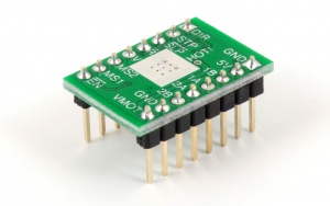
- MightyStep17 Stepper Driver - My re-designed and improved A4982 driver, fully MakerBot BotStep17 compatible
- MakerBot Replicator 1 Adapting A4988 Replacement Driver
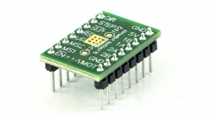
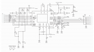
The official MightyBoard comes with BotStep17 Rev.E driver boards, designed by Harry Mulliken. It is based on the Allegro A4982 (not A4928 misnomer) motor driver and interface chip, in QFN package for better heat dissipation.
- The A4982 and A4988 can handle max. 2A output current per coil (bipolar motor has two coils) with sufficient active cooling [4], but a normal driver as-is is only designed to handle approx. 1A per coil
Setting up A4988 boards:
- The Vreg signal used for setting the motor current is replaced with a MS3 (Microstep 3) signal pin, either remove the pin or cut the trace to Vreg on the Mightyboard and solder the new MS3 signal to 5V to enable 1/16 steps
- Turn the trimpot to adjust the motor current limit (this replaces the Vreg functionality previously done digitally by the Makerbot firmware), a circled via on the bottom side of the board is Vref to calculate the current limit
- Adjust the current limit by turning the trimpot (on A4988 boards) until the equation Vref/(8xRsense) matches approx. 830mA
- Measure Vref by putting the positive prove on top of the trimpot and the negative on a common ground point
- Polulu: 0.35V/(8x0.05 Ohm) = 0.875mA
- Geeetech: 1.34V/(8x0.200 Ohm) = 0.8375mA
Compatible boards:
- MakerBot BotStep17 Rev.E - Official Thingiverse files (schematic, BOM, layout) - local backup
- Original part, 0.270 Ohm sense resistors
- Direct drop-in replacement
- MightyStep17 A4982 Stepper Driver
- Fully MakerBot BotStep17 compatible
- HoekDrive17 compatible driver
- Direct drop-in replacement
- Hard to get hold of, sold out
- Pololu A4988 Stepper Motor Driver Carrier - different chip but compatible
- Not direct drop-in, pin header is soldered the other way around
- Current Limit Imax = Vref/(8x0.05Ohm)
- Geeetech A4988
- Not direct drop-in, pin header is soldered the other way around
- Sense resistor is 0.200 Ohm
BotStep17 Specification from Thingiverse page:
- Controller chip: Allegro A4982
- Max. Motor Voltage: VBB 28V
- Max. Logic Voltage: VDD 5.5V
- Max. Power Dissipation (no heatsink): 2.0W
- Default Vref voltage: VDD x 0.267 +- 2%
- Default motor current: Vref/2.16 +-10%
- Rosc set to GND (mixed decay mode)
- Step resolution: 1/1, 1/2, 1/4, 1/16 - MakerBot firmware uses 1/16 steps, hard-wired on the Mightyboard
Fixed by internal resistors 33K to VDD, 12K to GND, may be changed on pin Vreg.
- Imax = Vref/(8x0.270 Ohm) - the sense resistor will change between MakerBot A4982 (0.270 Ohm), Geeetch A4988 (0.200 Ohm) and Pololu A488 (0.05 Ohm), check the board for confirmation
- Fixed by internal 0 Ohm resistor
- Makerbot firmware A4982 Vref defaults:
- The MCP4018T-502E/LT digipots value is set to 118 for X, Y, A and B which gives Vref 1.75V (810mA max.), and 40 for Z which gives 0.60V (278mA max.).
Microstep Resolution Truth Table:
MS1 	MS2 	Microstep Resolution Excitation Mode
L 	L 	Full Step 2 Phase
H 	L 	Half Step 1-2 Phase
L 	H 	Quarter Step W1-2 Phase
H 	H 	Sixteenth Step 4W1-2 Phase
In an event that the BotStep burns out, to prevent 24V from back-feeding into the 5V rail, consider putting a Schottky-diode on the 5V rail. Either by cutting the trace or replacing the 5V pin on the Botstep with a diode [5]. Not necessarily required.
LCD interface
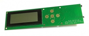
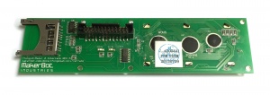
The LCD Interface Rev. B provides a display and buttons to control the 3D-printer directly. Connects to the Mightyboard via a 26-pin ribbon cable.
The board is fairly simple but has the LCD segment drivers directly integrated on the board, which makes repairing the LCD drivers very hard.
- 5 push-buttons with 5v pull-up
- New Haven ACM2004A FSW FGBW 4x20 character back-lite 5V LCD display
- New Haven ST7066U Dot Matrix LCD Controller/Driver
- AIP31063 Segment Drivers
- HEF4094B 8-stage serial shift register for the LCD driver
- SD Card Slot, Push In/Push Out, Reverse
- SN74AHC125D quadruple bus buffer gates for 3.3v levels for the SD card slot
Heater board
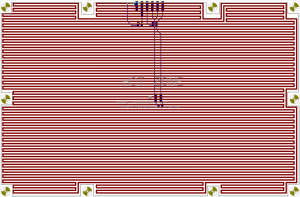
The hated build platform is a PCB board and aluminum sandwich with a 6-pin connector.
It uses a plain maze of copper traces as heater elements. Powered by 24V power and measured by a thermistor on the other side.
- Header element resistance 3.9 Ohm, at 24V makes 6.2A or 148W
- Thermistor 100K 1206 1%, most probable the NTHS1206N01N1003FE, B value 3964 K
Heated build platform connector replacement
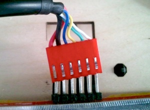
The connector on the heated build platform can sometimes be misaligned and cause a connection with bad contact, leading to resistance and thermal heat production. Replacing the connector and header is relatively simple with a plier and soldering iron.
- Connector (1x): Molex 09-50-7061 HSG 6P W/O LKG RAMP CONNECTOR
- Pin header (1x) - better: Molex 26-61-4060 VERT PCB 6P FRICTION LOCK HEADER Gold plated
- Pin header (1x) - same as original: Molex 41671-0005 3.96mm BRKWY HDR 6P Gold plated
- Power cable crimps (2-6x): Molex 08-58-0122 TERMINAL 18-20 BULK CRIMP Gold plated
Pin-out:
- SIG - Thermistor voltage - White
- GND - Common ground - Green
- GND - Common ground - Yellow - Note: can be swapped with green GND, makes no difference
- 5V - Supply power - Blue
- +24V - Power positive - Black
- HEAT- - Power negative - Red - Note: can be swapped with +24V, makes no difference, used to heat copper
A better solution, is to by-pass the Mightyboard entirely and wire the 24V from the power supply directly to the HBP by soldering to them to the traces. Alternatively, parallel the load from the power supply by using the normal power in connector and also use the screw terminals on the "CS-FAN" connector to supply 24V to the board.
Mechanical end-stops
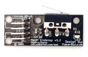
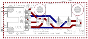
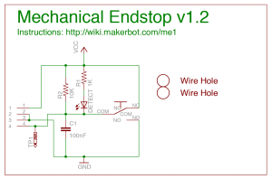
There are four end-stops used on the Replicator 1; x-max, y-max and z-min.
To prevent over-loading the 5V regulator in an event that the cable wears out and 5V shorts to GND, remove and isolate the white 5V pin from the locking-connector, or add a 1k resistor in series to limit the current [6]. This pin is used to pull-up the signal pin and light up the red-LED on the end-stop board, but the former is done in the main microcontroller. You can test if the cable is shorted by checking the continuity between the white and any of the two black wires, it should be open.
Power supply replacement
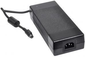
The Replicator 1 came with a good 24V 9.2V PSU. A replacement should be 24V and 10A or better, the heated build platform by itself uses 150W of power.
Original:
- Mean Well GS220A24-R7B 221W 24V 9.2A desktop AC adapter - UL/TUV certified
- Power plug: KYCON KPPX-4P DIN 4-pin with lock type, rated for 20V 7.5A
Replacement:
- Meanwell SE-350-24 350W 24V 14.6A switching power supply [7]
- Power inlet socket: Schurter 6100.3300 AC Power Entry Modules PNL SCREW-ON .250 QC
Belt replacements
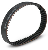
The Replicator 1 has GT2 belts from both SDP/SI and Gates. SDP/SI actually puts the part number on the belt, while Gates does not put the part numbers on - you have to infer it.
Recommended to get them via the SDI SI store.
- Y axis, left hand side: SDP A 6R51M293060 Made in Japan
- "2MR-586-06" and "A 6R51M293060" is the inferred part number you need to look for
- GT2 -> 2mm pitch; "293 grooves; 586 mm length; 6.0 mm wide
- 'Y axis, right hand side: Gates GT 2MR293 Made in Japan
- "2MR-586-06" and "A 6R51M293060" is the inferred part number you need to look for
- 2MR -> GT2 -> 2mm pitch; 293 grooves; 586 mm length; 6.0 mm wide
- X axis, extruder carriage: Gates GT 2MR424
- "2MR-848-06" and "A 6R51M424060" is the inferred part number you need to look for
- 2MR -> GT2 -> 2mm pitch; 424 grooves; 848 mm length; 6.0 mm wide
- Y axis, belt on back stepper motor, small: Gates PGGT 2MR-166
- "2MR-166-06" and "A 6R51M083060" is the inferred part number you need to look for
- 2MR -> GT2 -> 2mm pitch; 83 grooves; 166 mm length 6.0 mm wide
For Replicator 2/2X, these machines use the same X and Y main belts, but 125 grooves on the small belt instead - "2MR-250-06" and "A 6R51M125060" [8].
