Electric Hoverboard Monorover R2 Teardown: Difference between revisions
No edit summary |
No edit summary |
||
| (19 intermediate revisions by the same user not shown) | |||
| Line 1: | Line 1: | ||
[[Image:hoverboard_content.jpg|400px|right]][[Image:hoverboard_left_platform.jpg|400px|right]][[Image:hoverboard_right_platform.jpg|400px|right]]The Monorover R2 is an electric self balancing hoverboard - based on two individual motors joint at a central axis-point. It is an efficient way to get around your neighborhood, park, to the shop, in the mall and other relatively flat surface areas. | [[Image:hoverboard_content.jpg|400px|right]][[Image:hoverboard_left_platform.jpg|400px|right]][[Image:hoverboard_right_platform.jpg|400px|right]][[Image:hoverboard_operation.jpg|400px|right]][[Image:hoverboard_overview_diagram.png|400px|right]]The Monorover R2 is an electric self balancing hoverboard - based on two individual motors joint at a central axis-point. It is an efficient way to get around your neighborhood, park, to the shop, in the mall and other relatively flat surface areas. | ||
* Purchased from [http://www.aliexpress.com/item/New-Pattern-Mobility-Scooter-Swing-Car-Two-Wheel-Scooter-Self-Balancing-Electric-Vehicle-Motorcycle-Light-and/32328839149.html Wuxi Oriental Star Metal Science And Technology Co., Ltd.] at 158.00USD and 169.46USD shipping cost, plus approx. 82.00USD in duties. | |||
* [http://beta.ivc.no/hoverboard/hoverboard-white-documents.pdf Hoverboard White Manual - PDF] | |||
== Usage specifications == | == Usage specifications == | ||
* Road surface: relatively flat, no more than +-25mm bumps (asphalt, grass, fine gravel) | * Road surface: relatively flat, no more than +-25mm bumps (asphalt, grass, fine gravel) | ||
* Maximum speed: | * Maximum speed: 12km/h (tested), begins to beep - 15km/h (tested) comfortably possible | ||
* Max riding angle: approx. 15°, vary depending on rider's weight, road condition and temperature | * Max riding angle: approx. 15° to 20°, vary depending on rider's weight, road condition and temperature (19° tested) | ||
* Range per charge: 20km | * Range per charge: 20km | ||
* Ride height: 110 mm | * Ride height: 110 mm | ||
| Line 32: | Line 35: | ||
* Battery: Lithium-ion rechargeable 18650-cells, 10S2P 36V 4400mAh 158.4Wh pack with XT60 connector | * Battery: Lithium-ion rechargeable 18650-cells, 10S2P 36V 4400mAh 158.4Wh pack with XT60 connector | ||
* Charger: Lithium-ion charger 42V 2A 3-pin connector with built-in fan | * Charger: Lithium-ion charger 42V 2A 3-pin connector with built-in fan | ||
* Internal connectors: JST Sales America B4B-XH-A(LF)(SN) 2.5mm pitch | |||
* Dimension: 58.5 x 18.5 x 18.0 cm | * Dimension: 58.5 x 18.5 x 18.0 cm | ||
* Unit weight: 10kg | * Unit weight: 10kg | ||
* Manufacturer warranty: 1 year | * Manufacturer warranty: 1 year | ||
* Contents: 1x Electric Hoverboard, 1x User Manual & Warranty Card, 1x Worldwide AC Power Adapter Type according to your country | |||
<html><div style="clear:both"></div></html> | |||
== Battery == | == Battery == | ||
| Line 64: | Line 71: | ||
It connects to the unit with a keyed 3-pin (where 2-pins are used) connector and a threaded ring to secure it (unnecessary) to the socket. | It connects to the unit with a keyed 3-pin (where 2-pins are used) connector and a threaded ring to secure it (unnecessary) to the socket. | ||
Charging at a rate of 2 Amps per hour, it takes approx. 2h 12m to charge an entirely discharged battery. | |||
<html><div style="clear:both"></div></html> | <html><div style="clear:both"></div></html> | ||
== Limitations == | |||
It is important to realize the limitations of the motors and hall-effect sensors. Once the hoverboard reaches a certain speed threshold it looses track of the forward momentum and begins to tilt forward - making you fall off and the hoverboard to roll away from you. | |||
* Always limit your forward speed when the alarm starts to beep, any faster and it will loose track of your forward momentum | |||
== Control boards == | == Control boards == | ||
| Line 71: | Line 85: | ||
There are three circuit boards on the unit, one main board and two auxiliary boards on each axis-half. The aux. boards controls and connects the front lights, status/battery indicator panels, pedal platform opto interrupters and, most importantly, the accelerometer sensor. | There are three circuit boards on the unit, one main board and two auxiliary boards on each axis-half. The aux. boards controls and connects the front lights, status/battery indicator panels, pedal platform opto interrupters and, most importantly, the accelerometer sensor. | ||
The main board contains the main controller, 3-phase motor drivers, hall-effect inputs, current sensors, battery voltage | The main board contains the main controller, 3-phase motor drivers, hall-effect inputs, current sensors, battery voltage tap, power switch input, alarm buzzer and various voltage regulators, op-amps and protection circuitry. Bottom side has no components. The motor driver transistors are mounted on a separate heat-sink metal plate which mounts onto the frame. | ||
The front lights circuit board has 3-pin input (LED1, LED2, GND). It seems that the dual LED functionality is not in use, on this model. This could be used to change the intensity, color or other uses. | The front lights circuit board has 3-pin input (LED1, LED2, GND). Each line has a string of LEDs attached. It seems that the dual LED functionality is not in use, on this model. This could be used to change the intensity, color or other uses. | ||
=== Main board === | === Main board === | ||
| Line 90: | Line 104: | ||
* Solid green - Battery power level OK | * Solid green - Battery power level OK | ||
* Blinking green - Battery power level under 25% | * Blinking green - Battery power level under 25% | ||
* Solid red and beeping - Battery lower than | * Solid red and beeping - Battery lower than 10%, recharge immediately | ||
'''Status indicator:''' | '''Status indicator:''' | ||
* Solid green - Tilt sensor and driver controller OK | * Solid green - Tilt sensor and driver controller OK | ||
* Blinking green - Tilt sensor error | * Blinking green - Tilt sensor error | ||
* Solid red and beeping - Tilt | * Solid red and beeping - Tilt sensor not ready, outside working range | ||
* Blinking yellow - Charger connected and charging battery | * Blinking yellow - Charger connected and charging battery | ||
Latest revision as of 12:36, 27 January 2019
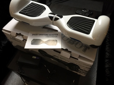
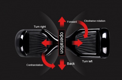
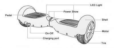
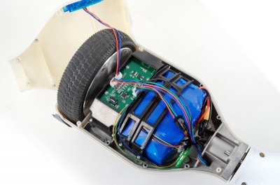
The Monorover R2 is an electric self balancing hoverboard - based on two individual motors joint at a central axis-point. It is an efficient way to get around your neighborhood, park, to the shop, in the mall and other relatively flat surface areas.
- Purchased from Wuxi Oriental Star Metal Science And Technology Co., Ltd. at 158.00USD and 169.46USD shipping cost, plus approx. 82.00USD in duties.
- Hoverboard White Manual - PDF
Usage specifications
- Road surface: relatively flat, no more than +-25mm bumps (asphalt, grass, fine gravel)
- Maximum speed: 12km/h (tested), begins to beep - 15km/h (tested) comfortably possible
- Max riding angle: approx. 15° to 20°, vary depending on rider's weight, road condition and temperature (19° tested)
- Range per charge: 20km
- Ride height: 110 mm
- Ground clearance: 30 mm
- Turning radius: 0°, on the spot
- Tire-to-chassis clearance: 5 mm
- Max load: 100kg
- Min load: 20kg, otherwise starts to oscillate
- Charge time: 2 to 3 hours using 42V 2A charger
- Modes: standby, activated, automatic shutdown after 2 minutes standby
Technical specifications
- Released: January 2015
- Product code: DAT-N1
- Manufacturer: Shanghai DAT Electric Vehicle
- Type: self balancing hoverboard
- Main controller: STM32F103 ARM Cortex-M3 core
- Balancing controllers: 2x STM32FEB ARM Cortex-M3 core
- Balancing sensors: 2x InvenSense MPU-605 MEMS 3-axis gyroscope and 3-axis accelerometer
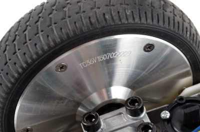
- Motor: 2x direct drive 3-phase brushless DC electric wheel hub motors, 36V 350W, 700W total
- Tire type: non-pneumatic rubber tire, road pattern
- Tire size: 7-inch / 170 mm
- Activate: switch pads for both feet
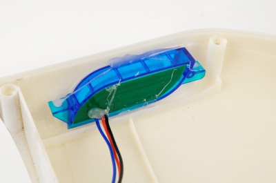
- Lights: 2x blue tinted LED windows
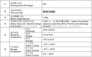
- Work temperature: -10°C to 40°C, peak performance at 10 to 30°C
- Environment protection: IP54 - dust protected, splashing of water
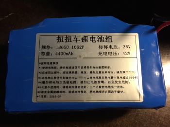
- Battery: Lithium-ion rechargeable 18650-cells, 10S2P 36V 4400mAh 158.4Wh pack with XT60 connector
- Charger: Lithium-ion charger 42V 2A 3-pin connector with built-in fan
- Internal connectors: JST Sales America B4B-XH-A(LF)(SN) 2.5mm pitch
- Dimension: 58.5 x 18.5 x 18.0 cm
- Unit weight: 10kg
- Manufacturer warranty: 1 year
- Contents: 1x Electric Hoverboard, 1x User Manual & Warranty Card, 1x Worldwide AC Power Adapter Type according to your country
Battery
Specifications:
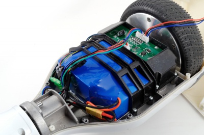
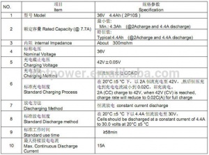
- Type: Lithium-ion rechargeable 18650-cell battery pack
- Voltage: 36V
- Capacity: 4400 mAh
- Dimensions: 135 x 85 x 55 mm
- Connector: XT60
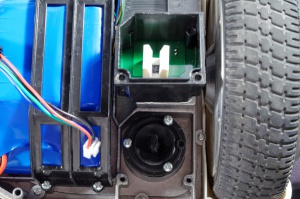
The power source in the hoverboard is a single 18650-cell based Lithium-ion battery pack with XT60 connectors - no balancing leads.
Upgrades
The 18650 pack can be upgraded to any battery pack with 36V output voltage, meaning you can use two 18V backs in parallel to get 36V. Any capacity will work, minimum 3000mAh recommended, as long as the size does not exceed 135x85x58mm.
The following suggestions can be connected two in parallel and externally charged.
- 2x Turnigy nano-tech 3300mah 5S 65C Lipo Pack - total 6600 mAh capacity, theoretically
- 2x Turnigy nano-tech 3850mah 5S 65C Lipo Pack - total 7700 mAh capacity, theoretically
- 2x Wild Scorpion 18.5V 4200mAh 30C MAX 40C 5S - total 8400 mAh capacity, theoretically
- 2x Venom 15020 18.5V 5000mAh 25C 1P 5S LiPo Battery VNR15020 - total 10000 mAh capacity, theoretically
Charger
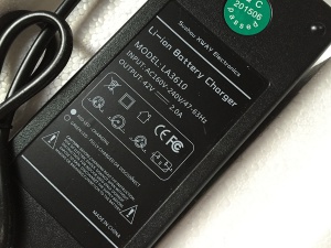
The kit includes a (weird) 160 to 240V Lithium-ion 42V 2A charger. An LED light illuminates red when the battery is charging and green when it is complete or idle.
It connects to the unit with a keyed 3-pin (where 2-pins are used) connector and a threaded ring to secure it (unnecessary) to the socket.
Charging at a rate of 2 Amps per hour, it takes approx. 2h 12m to charge an entirely discharged battery.
Limitations
It is important to realize the limitations of the motors and hall-effect sensors. Once the hoverboard reaches a certain speed threshold it looses track of the forward momentum and begins to tilt forward - making you fall off and the hoverboard to roll away from you.
- Always limit your forward speed when the alarm starts to beep, any faster and it will loose track of your forward momentum
Control boards
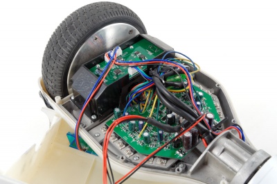
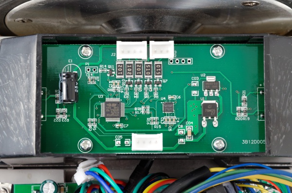
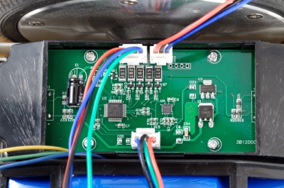
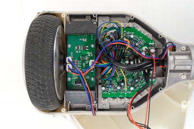
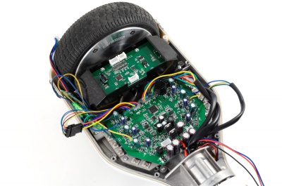
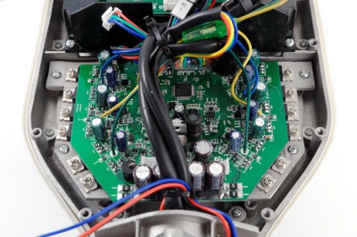
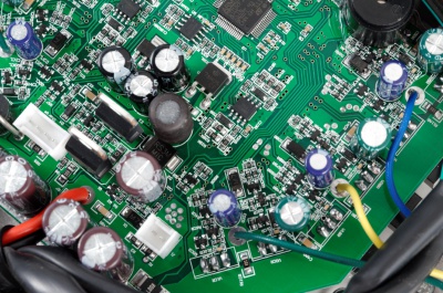
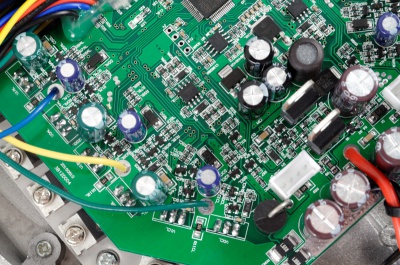
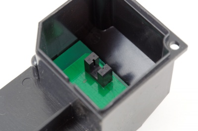
There are three circuit boards on the unit, one main board and two auxiliary boards on each axis-half. The aux. boards controls and connects the front lights, status/battery indicator panels, pedal platform opto interrupters and, most importantly, the accelerometer sensor.
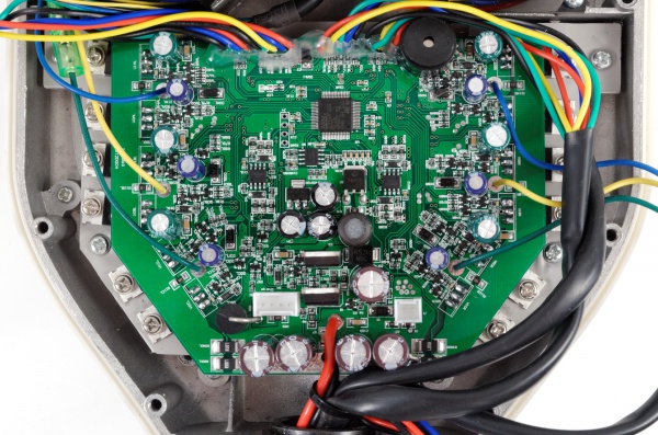
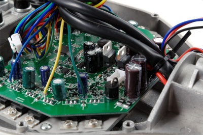
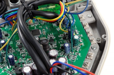
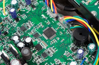
The main board contains the main controller, 3-phase motor drivers, hall-effect inputs, current sensors, battery voltage tap, power switch input, alarm buzzer and various voltage regulators, op-amps and protection circuitry. Bottom side has no components. The motor driver transistors are mounted on a separate heat-sink metal plate which mounts onto the frame.
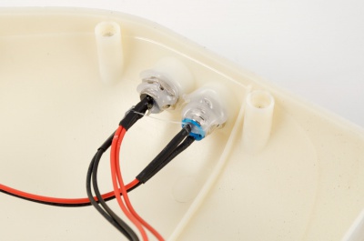
The front lights circuit board has 3-pin input (LED1, LED2, GND). Each line has a string of LEDs attached. It seems that the dual LED functionality is not in use, on this model. This could be used to change the intensity, color or other uses.
Main board
Auxiliary boards
LED status indicators
Battery indicator:
- Solid green - Battery power level OK
- Blinking green - Battery power level under 25%
- Solid red and beeping - Battery lower than 10%, recharge immediately
Status indicator:
- Solid green - Tilt sensor and driver controller OK
- Blinking green - Tilt sensor error
- Solid red and beeping - Tilt sensor not ready, outside working range
- Blinking yellow - Charger connected and charging battery
Front lights:
- No lights - Pad switch off, standby
- Blue lights - Pad switch active, wheel ready
- Blinking lights - Turning left/right
Calibrate accelerometer offsets
The factory setup comes with the level/zero platform tilt already calibrated. But you can re-calibrate the hoverboard at any time using the power button, hold for 5 seconds.
- Use a bobble leveler or your phone for reference
- Put both platforms/pedals in zero offset to each other
- Put the leveler on the flat surface on one of the platforms/pedals
- Press and hold the power button for 5 seconds until an audioable confirmation is heard
- The front lights will blink when the calibration is done
- Turn off and on the hoverboard to use the new calibration offsets
Pedal platform stub fix
There are two rubber stubs per platform (front and back section) which interrupts the ST150 opto sensor, but sometimes they catch on the side of the sensor and gets squeezed into position. This can lead to damage to the sensor over time and it makes an annoying audible sound.
- Remove the aux board cover to expose the opto sensors
- Download this hoverboard opto sensor fix STL model and print 4 pieces on an 3D printer
- Insert them onto the opto sensors, no glue necessary
- Reassembly, fixed!
Tips and tricks
- To silence the beeper slightly, put a piece of tape/masking tape over the piezoelectric buzzer
- Remove the rattling noise from the free-moving washer in the axis-point, put a piece of 1mm round plastic between the limit bolt and the axis - or download and print this STL model
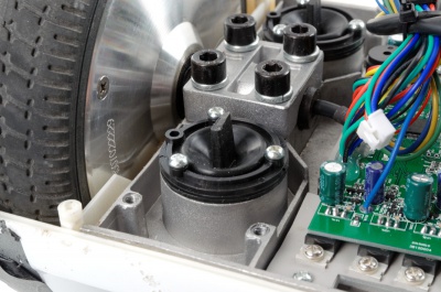
- The motor axis can sometimes come loose and make an klang-klang noise on sudden stops, remove the aux. board cover, release the four hex screws, add a piece of hard rubber or foam between the axis and top metal plate, and secure firmly
- Remove the snapping sound from the pedal platforms by mounting a funnel/guide piece over the opto interrupters
- Put a Mylar sheet underneath the battery to minimize scratching on the frame
- Minimize battery movement by pushing a piece of cotton or foam between inner side of the battery and frame
- Use a timer to charge the battery, 3 hours max., to turn off the trickle charge
- Turn off or disable the blue front lights by disconnecting the cables leading to the balance controller for each wheel
- To furhter improve the ripple and noise isolation, add capacitors on the unpopulated pads marked C## (# is a number), voltage rating double of what is measured on the line
