Xbox 360 Downgrader Hardware: Difference between revisions
No edit summary |
|||
| (38 intermediate revisions by the same user not shown) | |||
| Line 1: | Line 1: | ||
The downgrader hardware can be built in a day or two from | The downgrader hardware can be built in a day or two from easy-to-find parts. Infectus is rumored to released a daughter board that will interface with the Infectus chip for those not into building the hardware themself. | ||
== Parts == | |||
This is the BOM for my downgrader. I used a resonator instead of a crystal for the clock signal. The RS232 Rx and Tx LEDs can be removed because they turned out to be practically useless. | |||
The article numbers are from the Scandinavian electronic supplier [http://www.elfa.se/en/ ELFA]. | |||
* 1x 4831384 Prototyping board 100x160 mm | |||
* 1x 7319874 PIC16F876A-I/SP DIL28 | |||
* 2x 7301500 LM339N quad comparator DIL14 | |||
* 1x 7332323 MAX3232CPE RS232 transceiver DIL16 | |||
* 1x 7350317 74HC08N 4x 2-in AND gate DIL14 | |||
* 1x 7470248 20.00MHz resonator 3-pin (or crystal + 2x 22nF capacitors) | |||
* 1x 4408407 D-Sub 9-pin Space-Save | |||
* 2x 4408449 Locknut D-Sub | |||
* 1x 2553071 Extension cable 9-pin D-Sub | |||
* 1x 3565751 Keyboard switch 4.5 mm | |||
* 3x 4813564 IC-socket 14-pin DIL | |||
* 1x 4813580 IC-socket 16-pin DIL | |||
* 1x 4813721 IC-socket 28-pin DIL | |||
* 6x 6565659 Ceramic capacitor 0,1uF/50V | |||
* 23x 6010490 Resistor 1,0k ohm 1/4W | |||
* 1x 6010573 Resistor 4,7k ohm 1/4W | |||
* 1x 6010615 Resistor 10k ohm 1/4W | |||
* 1x 4310827 IDC Connector female plug 16-pin | |||
* 1x 4311627 IDC Connector male socket 16-pin | |||
* 1x 5566054 Ribbon cable grey 16-core 1 meter | |||
* 1x 4205209 DC-plug 1.3 mm | |||
* 1x 4205407 DC-jack 1.3 mm | |||
* 2x 7503857 EL383GD LED 5 mm green | |||
* 1x 7503899 EL383YD LED 5 mm yellow | |||
* 1x 7503865 EL383HD LED 5 mm red | |||
* 1x 4370334 Pin header 2.54 mm 2x20-pins | |||
* 4x 4371102 Jumper blue open | |||
== Schematics == | == Schematics == | ||
There are two good schematics, one from the creator of the downgrader | There are two good schematics, one from the creator of the downgrader (robinsod) and one from an enthusiast (rufusb). | ||
* [http://beta.ivancover.com/xbox360/timing_attack/docs/schematic.pdf Robinsod drawing] [http://www.xboxhacker.net/index.php?topic=8555.msg54228#msg54228] | |||
* [http://beta.ivancover.com/xbox360/timing_attack/docs/Schematic.pdf Robinsod's schematic] - [http://beta.ivancover.com/xbox360/timing_attack/docs/ideas.doc Internal notes] | |||
* [http://beta.ivancover.com/xbox360/timing_attack/docs/Schematic2.pdf Robinsod's schematic2] - [http://rapidshare.com/files/69716339/Schematics2-bom.rtf.html BOM (Bill Of Materials)] - [http://beta.ivancover.com/xbox360/timing_attack/docs/Downgrading_the_Xbox360.doc Public notes] - recommended | |||
* [http://beta.ivancover.com/xbox360/timing_attack/docs/xbox360_downgrader.pdf Rufusb professional drawn schematic] [http://www.xboxhacker.net/index.php?topic=8555.msg54294#msg54294] | |||
''Robinsod's schematic:'' | |||
[[Image:Timing attack schematic.PNG|650px]] | |||
== Programming PIC == | |||
Before installing the 16F876A PIC processor, a [http://www.microchipc.com/PIC16bootload/ bootloader] should be installed to make it easier to upload code and update code over the serial-port later, instead of a external programmer. | |||
I used a Piccolo / Pesto ISCP programmer to program the initial bootloader to the PIC. Any programmer with support for 16F876A should work. Make sure to first erase and then write the new code. | |||
The recommended bootloader package is [http://www.microchipc.com/PIC16bootload/PIC16F87xA_bootloader_v9-50.zip Shane Tolmie PIC bootloader v9.50] and specifically the ''''bootldr-16F876A-20MHz-56000bps.HEX'''' for this project (''\PIC bootloader\bootloader hex files for 16F87xA compatible bootloader\legacy''). The Downloader application to upload the HEX-code is also included in the package, look in 'Downloader Windows in Delphi' folder. | |||
Top side: | To use the bootloader, select the HEX-file, press 'Write' and then when it says 'Searching for bootloader', press the RESET-button on the downgrader to start the programming. | ||
''PIC programmer:'' | |||
[[Image:Piccolo big.jpg|350px]] | |||
== Building Hardware == | |||
A little planning should be done before building the hardware. Figure out how the positioning the chips and wire the connections. | |||
Equipment: | |||
* Solder iron 15-30 Watt | |||
* Solder rosin core 0.5-1.0 mm | |||
* Wire 25-30 AWG | |||
* Wire cutters and pliers | |||
''Top side:'' | |||
[[Image:Downgrader hardware top.jpg]] | [[Image:Downgrader hardware top.jpg]] | ||
Bottom side: | ''Bottom side:'' | ||
[[Image:Downgrader hardware bottom.jpg]] | [[Image:Downgrader hardware bottom.jpg]] | ||
== | == Installation == | ||
Bottom side (click for full resolution): | ''Bottom side (click for full resolution):'' | ||
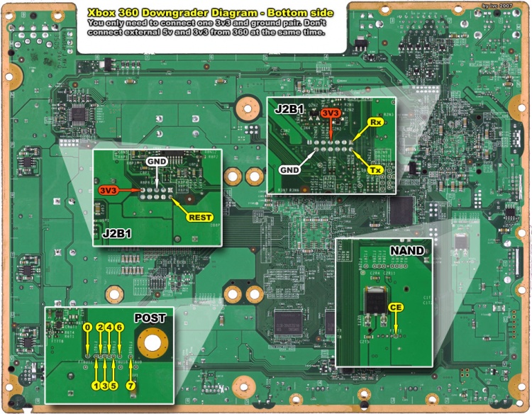
[[Image:Xbox360 downgrader diagram bottom.jpg|750px|Image:Xbox360 downgrader diagram bottom.jpg]] | [[Image:Xbox360 downgrader diagram bottom.jpg|750px|Image:Xbox360 downgrader diagram bottom.jpg]] | ||
Top side (click for full resolution): | ''Top side (click for full resolution):'' | ||
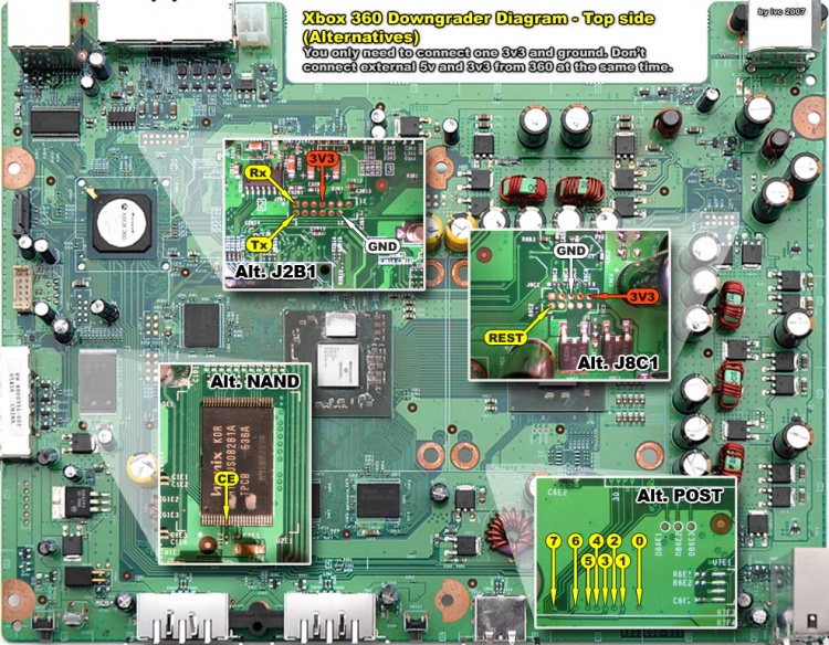
[[Image:Xbox360 downgrader diagram top.jpg|750px|Image:Xbox360 downgrader diagram top.jpg]] | [[Image:Xbox360 downgrader diagram top.jpg|750px|Image:Xbox360 downgrader diagram top.jpg]] | ||
== Installed == | |||
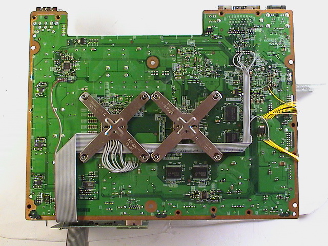
[[Image:Downgrader installed overview.jpg]] | |||
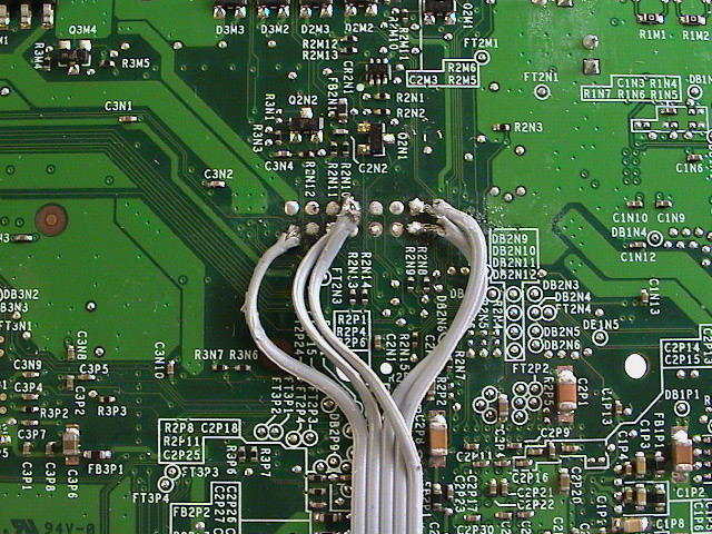
[[Image:Downgrader installed J2B1.jpg]] | |||
[[Image:Downgrader installed CE.jpg]] | |||
[[Image:Downgrader installed POST.jpg]] | |||
[[Image:Downgrader installed JTAG.jpg]] | |||
== Verification == | |||
=== Downgrader functions === | |||
To verify that the downgrader works and accepts commands sent over the serial port, check the following: | |||
# Open HyperTerminal in Windows (Start -> Run -> hypertrm). | |||
# Make a new connection, give it a name, select the COM1 or COM2 port, click 'Restore Defaults', and open the connection. | |||
# Once connected, type ''''?'''' (questionmark). | |||
# The downgrader should respond ''''!0'''' or ''''!1'''' (JTAG reset line status, low/high). | |||
=== Xbox 360 functions === | |||
Install the downgrader using the installation diagram above. Double check that the wires going to the POST points are correct. | |||
# Turn off the Xbox 360 and connect the downgrader. | |||
# Open HyperTerminal in Windows (Start -> Run -> hypertrm). | |||
# Make a new connection, give it a name, select the COM1 or COM2 port, click 'Restore Defaults', and open the connection. | |||
# Once connected, type ''''p'''' and the downgrader should respond ''''POST Mon (Reset PIC to exit)''''. | |||
# Power on the Xbox 360 and watch the terminal for POST codes. | |||
If the patched 1888 image is flashed to the NAND, the following sequence should be repeated 4 times before RRoD starts to blink: | |||
P 00 | |||
P 10 | |||
P 11 | |||
P 12 | |||
P 18 | |||
P 19 | |||
P 1A | |||
P 1B | |||
P 1C | |||
P 1D | |||
P 1E | |||
P 20 | |||
P 21 | |||
P A4 | |||
== Downgrading == | |||
* [[Xbox 360 Timing Attack]] | |||
== Troubleshooting == | |||
* Problem: Downgrader is non-responsive when connected to terminal application. | |||
* Fix: Make sure the serial-port is enabled in the BIOS and that you get a response if you loop the Tx and Rx pins together (pin 2 and 3). If you're not using a null-modem cable, try to switch pin 2 and 3 on the downgrader so the RS232 pin 14 is connected to pin 2 and pin 13 is connected to pin 3 on the D-SUB female connector. | |||
* Problem: Serial port loopback works fine but the downgrader is still not working. | |||
* Fix: Verify the entire board for shorts and bridges. Double check that every connection is correctly wired, A -> B. | |||
* Problem: When trying to upload the HEX-code via bootloader, it aborts and shows an error message. | |||
* Fix: Try to add a capacitor between the power and ground near the RS232 and all the other IC-chips to stop ripples on power-on and during operation. If electrolyte capacitors is used, make sure to use the correct orientation, negative to ground. | |||
* Problem: The POST sequence does not has the same values as mentioned. | |||
* Fix: Make sure the POST connections are soldered to the correct points and not mirrored or bridged. | |||
* Problem: Error A4 when starting DGTool.exe and beginning timing attack. | |||
* Fix: Check the line between the CCP2 on the PIC and OUT on the 74HC08N AND-gate, and that the INPUTS for the AND-gate are connected to POST pin 0 and 5. CCP2 is used to trigger the falling edge of a measurement, when the post A4 is reported (22, 2E, or 2F is reported afterwards on normal boot). | |||
* Problem: Error 00 reported. | |||
* Fix: No connection, check all POST points. | |||
Latest revision as of 13:35, 4 February 2010
The downgrader hardware can be built in a day or two from easy-to-find parts. Infectus is rumored to released a daughter board that will interface with the Infectus chip for those not into building the hardware themself.
Parts
This is the BOM for my downgrader. I used a resonator instead of a crystal for the clock signal. The RS232 Rx and Tx LEDs can be removed because they turned out to be practically useless.
The article numbers are from the Scandinavian electronic supplier ELFA.
- 1x 4831384 Prototyping board 100x160 mm
- 1x 7319874 PIC16F876A-I/SP DIL28
- 2x 7301500 LM339N quad comparator DIL14
- 1x 7332323 MAX3232CPE RS232 transceiver DIL16
- 1x 7350317 74HC08N 4x 2-in AND gate DIL14
- 1x 7470248 20.00MHz resonator 3-pin (or crystal + 2x 22nF capacitors)
- 1x 4408407 D-Sub 9-pin Space-Save
- 2x 4408449 Locknut D-Sub
- 1x 2553071 Extension cable 9-pin D-Sub
- 1x 3565751 Keyboard switch 4.5 mm
- 3x 4813564 IC-socket 14-pin DIL
- 1x 4813580 IC-socket 16-pin DIL
- 1x 4813721 IC-socket 28-pin DIL
- 6x 6565659 Ceramic capacitor 0,1uF/50V
- 23x 6010490 Resistor 1,0k ohm 1/4W
- 1x 6010573 Resistor 4,7k ohm 1/4W
- 1x 6010615 Resistor 10k ohm 1/4W
- 1x 4310827 IDC Connector female plug 16-pin
- 1x 4311627 IDC Connector male socket 16-pin
- 1x 5566054 Ribbon cable grey 16-core 1 meter
- 1x 4205209 DC-plug 1.3 mm
- 1x 4205407 DC-jack 1.3 mm
- 2x 7503857 EL383GD LED 5 mm green
- 1x 7503899 EL383YD LED 5 mm yellow
- 1x 7503865 EL383HD LED 5 mm red
- 1x 4370334 Pin header 2.54 mm 2x20-pins
- 4x 4371102 Jumper blue open
Schematics
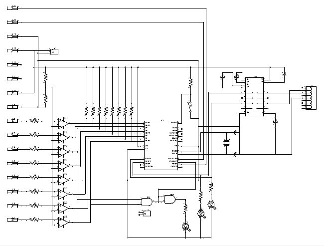
There are two good schematics, one from the creator of the downgrader (robinsod) and one from an enthusiast (rufusb).
- Robinsod drawing [1]
- Robinsod's schematic - Internal notes
- Robinsod's schematic2 - BOM (Bill Of Materials) - Public notes - recommended
- Rufusb professional drawn schematic [2]
Robinsod's schematic:
Programming PIC
Before installing the 16F876A PIC processor, a bootloader should be installed to make it easier to upload code and update code over the serial-port later, instead of a external programmer.
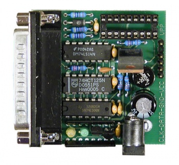
I used a Piccolo / Pesto ISCP programmer to program the initial bootloader to the PIC. Any programmer with support for 16F876A should work. Make sure to first erase and then write the new code.
The recommended bootloader package is Shane Tolmie PIC bootloader v9.50 and specifically the 'bootldr-16F876A-20MHz-56000bps.HEX' for this project (\PIC bootloader\bootloader hex files for 16F87xA compatible bootloader\legacy). The Downloader application to upload the HEX-code is also included in the package, look in 'Downloader Windows in Delphi' folder.
To use the bootloader, select the HEX-file, press 'Write' and then when it says 'Searching for bootloader', press the RESET-button on the downgrader to start the programming.
PIC programmer:
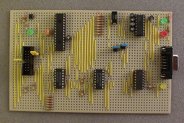
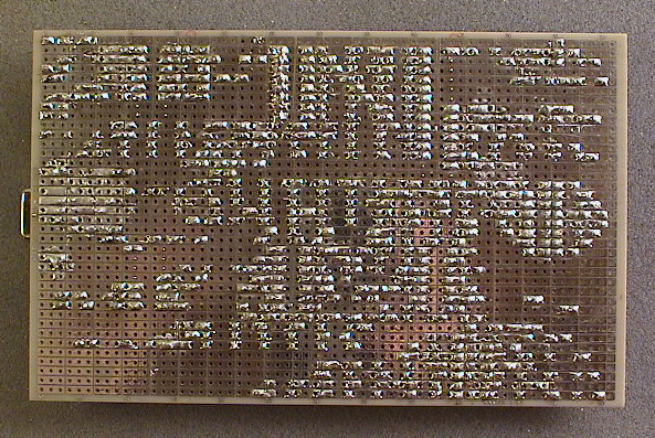
Building Hardware
A little planning should be done before building the hardware. Figure out how the positioning the chips and wire the connections.
Equipment:
- Solder iron 15-30 Watt
- Solder rosin core 0.5-1.0 mm
- Wire 25-30 AWG
- Wire cutters and pliers
Top side:
Bottom side:
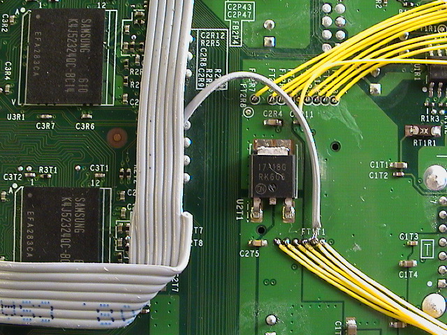
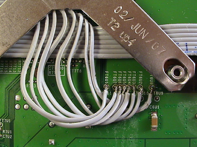
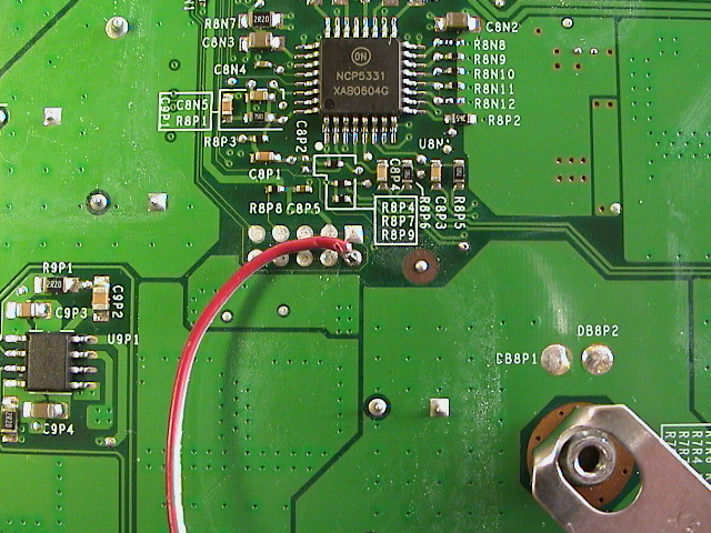
Installation
Bottom side (click for full resolution):
Top side (click for full resolution):
Installed
Verification
Downgrader functions
To verify that the downgrader works and accepts commands sent over the serial port, check the following:
- Open HyperTerminal in Windows (Start -> Run -> hypertrm).
- Make a new connection, give it a name, select the COM1 or COM2 port, click 'Restore Defaults', and open the connection.
- Once connected, type '?' (questionmark).
- The downgrader should respond '!0' or '!1' (JTAG reset line status, low/high).
Xbox 360 functions
Install the downgrader using the installation diagram above. Double check that the wires going to the POST points are correct.
- Turn off the Xbox 360 and connect the downgrader.
- Open HyperTerminal in Windows (Start -> Run -> hypertrm).
- Make a new connection, give it a name, select the COM1 or COM2 port, click 'Restore Defaults', and open the connection.
- Once connected, type 'p' and the downgrader should respond 'POST Mon (Reset PIC to exit)'.
- Power on the Xbox 360 and watch the terminal for POST codes.
If the patched 1888 image is flashed to the NAND, the following sequence should be repeated 4 times before RRoD starts to blink:
P 00
P 10
P 11
P 12
P 18
P 19
P 1A
P 1B
P 1C
P 1D
P 1E
P 20
P 21
P A4
Downgrading
Troubleshooting
- Problem: Downgrader is non-responsive when connected to terminal application.
- Fix: Make sure the serial-port is enabled in the BIOS and that you get a response if you loop the Tx and Rx pins together (pin 2 and 3). If you're not using a null-modem cable, try to switch pin 2 and 3 on the downgrader so the RS232 pin 14 is connected to pin 2 and pin 13 is connected to pin 3 on the D-SUB female connector.
- Problem: Serial port loopback works fine but the downgrader is still not working.
- Fix: Verify the entire board for shorts and bridges. Double check that every connection is correctly wired, A -> B.
- Problem: When trying to upload the HEX-code via bootloader, it aborts and shows an error message.
- Fix: Try to add a capacitor between the power and ground near the RS232 and all the other IC-chips to stop ripples on power-on and during operation. If electrolyte capacitors is used, make sure to use the correct orientation, negative to ground.
- Problem: The POST sequence does not has the same values as mentioned.
- Fix: Make sure the POST connections are soldered to the correct points and not mirrored or bridged.
- Problem: Error A4 when starting DGTool.exe and beginning timing attack.
- Fix: Check the line between the CCP2 on the PIC and OUT on the 74HC08N AND-gate, and that the INPUTS for the AND-gate are connected to POST pin 0 and 5. CCP2 is used to trigger the falling edge of a measurement, when the post A4 is reported (22, 2E, or 2F is reported afterwards on normal boot).
- Problem: Error 00 reported.
- Fix: No connection, check all POST points.
