Wbr-g54 firmware recovery: Difference between revisions
No edit summary |
|||
| (6 intermediate revisions by the same user not shown) | |||
| Line 27: | Line 27: | ||
Solder a resistor between all 4 connections and to the respective points below. The pin number is shown on the parallel connector. | Solder a resistor between all 4 connections and to the respective points below. The pin number is shown on the parallel connector. | ||
Parallel | Parallel JTAG | ||
Pin 2 DATA0 -> Resistor -> TDI | Pin 2 DATA0 -> Resistor -> TDI | ||
Pin 4 DATA2 -> Resistor -> TMS | Pin 4 DATA2 -> Resistor -> TMS | ||
Pin 3 DATA1 -> Resistor -> TCK | Pin 3 DATA1 -> Resistor -> TCK | ||
Pin 13 SELECT -> Resistor -> TDO | Pin 13 SELECT -> Resistor -> TDO | ||
Pin 25 GROUND -> GND (Common ground) | Pin 25 GROUND -> GND (Common ground) | ||
[[Image:Wrt54g jtag parallel connector.jpg]] | [[Image:Wrt54g jtag parallel connector.jpg|400px]] | ||
To find the JTAG points to solder the pin header to, check this [http://www.dd-wrt.com/wiki/index.php/JTAG_pinouts DD-WRT page] to find your model. For the WBR-G54 it's the normal JTAG pinout, 3: TDI, 5: TDO, 7: TMS, 9: TCK. More JTAG information is available at [http://wiki.openwrt.org/OpenWrtDocs/Customizing/Hardware/JTAG_Cable OpenWRT]. | To find the JTAG points to solder the pin header to, check this [http://www.dd-wrt.com/wiki/index.php/JTAG_pinouts DD-WRT page] to find your model. For the WBR-G54 it's the normal JTAG pinout, 3: TDI, 5: TDO, 7: TMS, 9: TCK. More JTAG information is available at [http://wiki.openwrt.org/OpenWrtDocs/Customizing/Hardware/JTAG_Cable OpenWRT]. | ||
| Line 69: | Line 69: | ||
Finally, to fix a corrupt NVRAM (In my case this was the reason the unit was bricked). | Finally, to fix a corrupt NVRAM (In my case this was the reason the unit was bricked). | ||
wrt54g.exe -erase: | wrt54g.exe -erase:nvram | ||
The result should be like this: | The result should be like this: | ||
| Line 97: | Line 97: | ||
[[Image:Wrt54g jtag tftp program.png]] | [[Image:Wrt54g jtag tftp program.png]] | ||
Now reboot the router once more and try to access OpenWRT via telnet, telnet 192.168.1.1. Use the ''mtd'' utility to | Now reboot the router once more and try to access OpenWRT via telnet, telnet 192.168.1.1. Use the ''mtd'' utility to erase and write a new flash image. | ||
== References == | == References == | ||
* [http://wiki.openwrt.org/OpenWrtDocs/Customizing/Hardware/JTAG_Cable OpenWRT JTAG cable] | * [http://wiki.openwrt.org/OpenWrtDocs/Customizing/Hardware/JTAG_Cable OpenWRT JTAG cable] | ||
* [http://wiki.openwrt.org/OpenWrtDocs/Hardware/Buffalo/WBR-G54 OpenWRT Buffalo WBR-G54] | |||
* [http://www.dd-wrt.com/phpBB2/viewtopic.php?p=78468 WBR-G54 Jtag recovery help] | * [http://www.dd-wrt.com/phpBB2/viewtopic.php?p=78468 WBR-G54 Jtag recovery help] | ||
* [http://www.fpga4fun.com/JTAG2.html How JTAG works] | * [http://www.fpga4fun.com/JTAG2.html How JTAG works] | ||
* [http://www.dd-wrt.com/phpBB2/viewtopic.php?t=25971&postdays=0&postorder=asc&start=90 List of CFE files for various routers] | |||
* [http://www.dd-wrt.com/wiki/index.php/Recover_from_a_Bad_Flash Recover from a Bad Flash] | |||
Latest revision as of 10:48, 9 August 2009
I recently tried to upgrade my Buffalo WBR-G54 running DD-WRT to the latest release of DD-WRT using the web flash form. Apparently what I thought was was the correct version immediately rendered the unit un-usable, aka not booting/brick.
Situation
The unit did not has a diag LED that usually shows the current stage in the boot sequence. This light did not show any activity after flashing the new firmware. The only LED activity was the ethernet port LEDs, blinking when there was some ARP/broadcast traffic on the network.
I also tried to flash a know working OpenWRT firmware image to the unit through TFTP and the boot_wait window, but without luck.
JTAG programming
The first stage in recovering the unit was to build a JTAG cable to program the flash image with a command-line program specially for the WRT54.
I didn't separate the JTAG build off to its own page, since the procedure is quite simple.
Build
There are three parts needed to build a simple JTAG cable:
- Parallel cable with a female connector (connect to computer)
- Four resistors (in the 100-150 Ohm range), alternatively two 220 Ohm in parallel for each connection
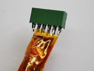
- Pin head and socket
Alternatively solder the resistors and parallel cable directly to the board.
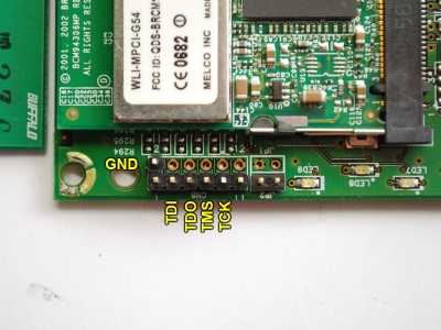
There are only 4 points needed to be able to program WRT54 based boards: TDI - TDO - TMS - TCK and ground [1].
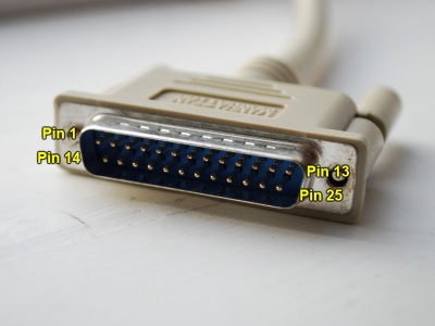
Solder a resistor between all 4 connections and to the respective points below. The pin number is shown on the parallel connector.
Parallel                           JTAG
Pin 2 DATA0     ->   Resistor ->   TDI
Pin 4 DATA2     ->   Resistor ->   TMS
Pin 3 DATA1     ->   Resistor ->   TCK
Pin 13 SELECT   ->   Resistor ->   TDO
Pin 25 GROUND   ->                 GND (Common ground)
To find the JTAG points to solder the pin header to, check this DD-WRT page to find your model. For the WBR-G54 it's the normal JTAG pinout, 3: TDI, 5: TDO, 7: TMS, 9: TCK. More JTAG information is available at OpenWRT.
After finishing up, verifying each connection with a multimeter to be sure everything is properly set up.
Program
There is a great application by hairydairymaid made specially for WRT54G based boards to program the flash via the Broadcom processor. Download the latest package from Openwrt download repository. It also includes a detailed PDF documentation.
Extract the package and go into the Windows-folder. The WRT54G requires a giveio.sys driver to be loaded to see the board. Copy giveio.sys to c:/windows/system32/drivers/ and execute the loaddrv.exe utility. In the top field add giveio.sys to the end of the path (c:/windows/system32/drivers/give.io) and press Start. It should report a successful load.
Now, open a command-prompt (Start -> run -> cmd) and go to the hairydairymain utility folder. Look through all the command arguments available by executing wrt54g.exe.
Connect the cable to the JTAG port and prepare this command line, but don't execute it:
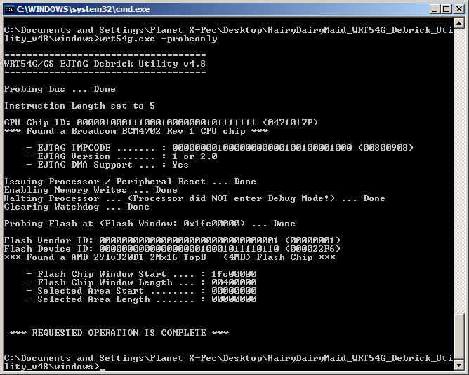
wrt54g.exe -probeonly
Now here comes the tricky part, 'disconnect the power to the unit, and at the same time you re-connect the power, press enter to execute the command. A half-second to early or too late, and the utility can't make the processor go into debug mode.
The result shown above will indicate that the JTAG communication went successful and accepts commands sent to it. If not, redo the tests and verify that the connections are OK and the computer has a working parallel port. If all else fails, the board might be at fault.
Before performing any harmful commands (erasing/flashing), create a backup of what's left of the CFE (Common Firmware Environment) and the NVRAM settings. Execute these two commands using the same un-plug / re-plug power method above:
wrt54g.exe -backup:cfe
wrt54g.exe -backup:nvram
The CFE is 256 KB and NVRAM 65 KB.
Finally, to fix a corrupt NVRAM (In my case this was the reason the unit was bricked).
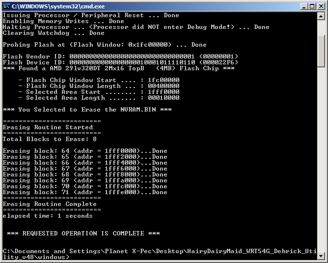
wrt54g.exe -erase:nvram
The result should be like this:
Try to cycle power and see if the boot process changes. Blinks red is a good sign that it boots to a certain stage and that recovering via TFTP should be possible.
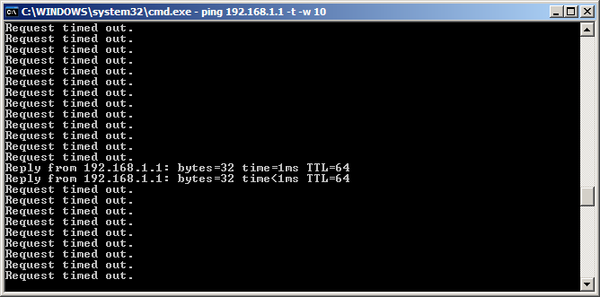
Open multiple ping processes on the known IP addresses that the board is configured for or default to. For my WBR-G54 I opened 192.168.11.1, 192.168.0.1, 192.168.1.1 and a couple of others, 192.168.222.1 and 192.168.50.1. But, you have to add each subnet to the network connection (eternet or wirless) so that the computer is local to those addresses. Short: Control panel -> Network connections -> Ethernet -> Properties -> TCP/IP -> Set the static IP address from DHCP (ipconfig) -> Advanced -> Add a new IP address to the top list.
ping -t -w 10 192.168.1.1
After plugging in power, the unit should respond after a few seconds if boot_wait is enabled and the TFTP server is working.
Recovering
Once TFTP is confirmed working, download a TFTP client (like this one) and open a command-prompt. In the meantime download a known to work firmware image, I used the OpenWRT openwrt-brcm-2.4-squashfs.trx firmware.
In the command-prompt enter this command but don't necessarily execute it quite yet.
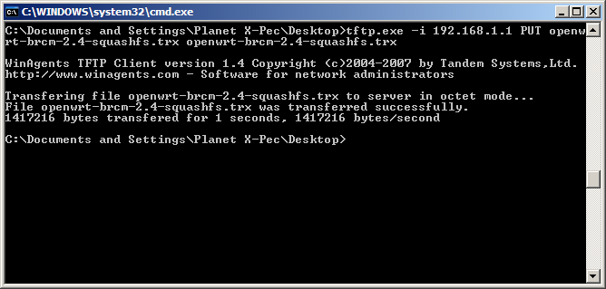
tftp.exe -i -v 192.168.1.1 PUT openwrt-brcm-2.4-squashfs.trx openwrt-brcm-2.4-squashfs.trx
Do the same trick as mentioned above, disconnect power, re-connect, and press enter to execute TFTP. If it didn't work the first time (usually never does), retry with slightly longer pause before pressing enter.
Now reboot the router once more and try to access OpenWRT via telnet, telnet 192.168.1.1. Use the mtd utility to erase and write a new flash image.
