Water Cannon Robot
Lately a friend of mine and I have talked about a new robotic arm project, as a summer activity. The idea is to create a stationary autonomous robot that can detect motion in the immediate vicinity and activate a pump to spray water in the direction of the object.
The project will be based on servos, brackets for mechanics, electric pump, motion and range sensors, video streaming, and java programming/sequencing.
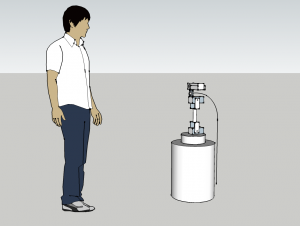
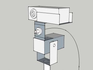
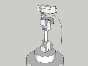
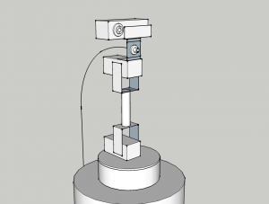
Sketch
This is a sketch drawn in Google Sketch-Up. Took approx. 1.5 hour to get the base done.
Build
Arm
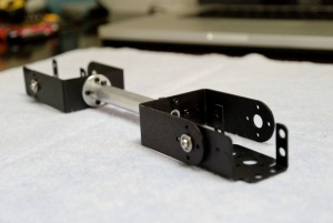
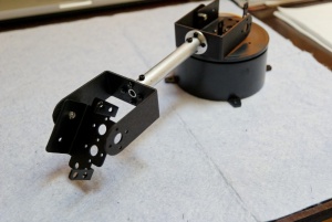
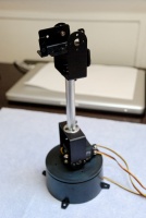
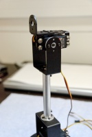
A company named Lynxmotion is offering an excellent range of parts to build a robotic arm. With all kinds of bracket and connectors, it's possible to build almost everything imaginable. Makes it very flexible to build things.
Box
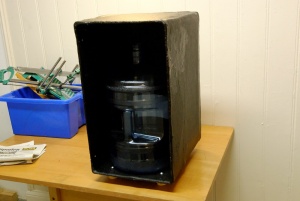
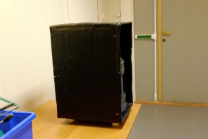
The box is made out of fiberglass and painted in black. The dimensions were approximations and given to a friend to work out of. It turned out to be quite a good fit and some room to spill.
Outter dimensions: 34.8 x 59.8 x 43.2 cm (WxHxD)
Inner dimensions: 32.6 x 57.5 x 41.5-42.0 cm (WxHxD) - Volume: 0,079 m3, 78 Liters
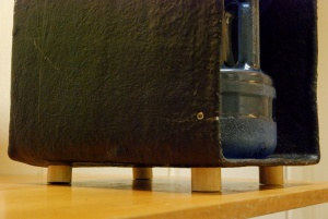
Attaching feet to the box was took some work to figure out as the bottom was not plane and level.
Equipment
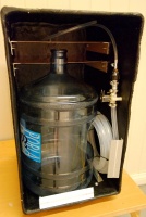
The following components has to fit inside the box:
- Pump components:
- Watertank 19L
- Hose 1/2" 12mm 5-8m for compression
- Solenoid Valve 1/" 12mm + 12V leads
- Hose Reduction Valve Kit 1/2" to 1/4"
- Electric and controller components:
- Leadbattery 12V 18Ah
- Eee PC 7" + 12V to 9V adapter
- WRT54GL Wireless Router + 12V leads
- Dual Relay board connected to RFID controller board
- Robot Arm components:
- Phidget RFID Controller Board w/USB cable
- Phidgets Advanced Servo Controller Board w/USB cable + 12V leads
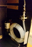
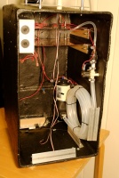
Pump, battery, solenoid valve, brackets mounts
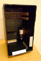
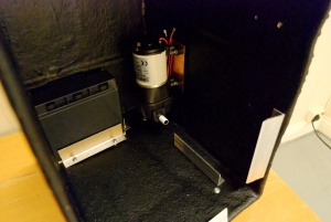
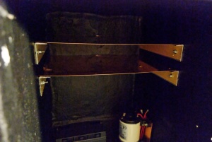
2009-07-26 - The mounts for all the pumping, battery, and shelving inside the box is done. The aluminum brackets ware leftovers from a stairs repair in the building, dimensions was great for this project.
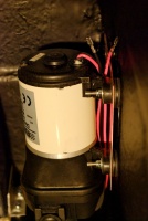
To avoid noise and vibration from the water pump, which is actually quite silent, I mounted a copper-plate between two rubber membranes. The feet on the pump is rubber and I added 4 rubber rings to the other side of the plate.
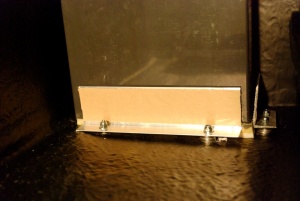
As the bottom of the box wasn't plane I used a few washers to lift the brackets to a level plane, especially the battery brackets. The battery bay has a foam matte to level the battery when it's seated.
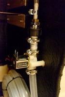
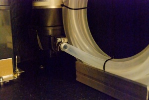
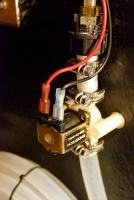
The water pumps is rated to provide 2.4 bar pressure. To even out the pressure, and to avoid having a expansion tank, I used 5 meter 1/2" water hose packed together to build up pressure and hopefully when the valve is released the pump can keep up. The valve is a simple 12V solenoid valve made out of plastic. It's closed by default and open when current is applied.
Arm mount
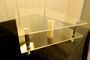
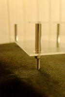
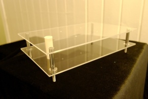
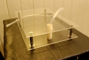
2009-07-31 - For the robot arm to look like it belongs on top of the rather large box, I decided to lift up a little by adding a 5 cm spacer made of two plexiglass sheets. It's put together by four screws and short pieces of 12 mm pipe holding the sheets apart. Nuts are pressing on the opposite side. Holes on top of the box makes it possible to install and fasten it. To make the surface on the top sheet smooth, the screw holes have been drilled out in an inverted cone shape.
A fifth hole is used to feed to control cables and water hose. A guide pipe made of plastic is just long enough to rest on top of the box between the sheets. The diameter of the hole in the plexiglass sheets are 20 mm and 16 mm on the box, this allows the cables to route through but not the guide pipe.
This setup makes it feel clean and I think it looks pretty cool too.
Wiring
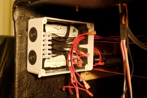
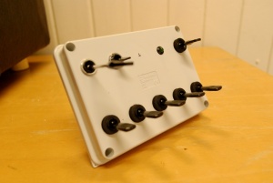
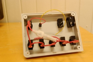
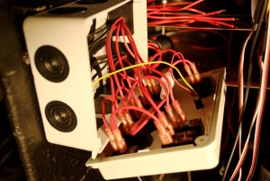
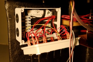
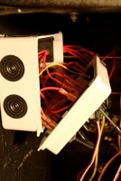
2009-08-08 - To control the power to all the devices in the box, each device has its own switch to turn on/off power by flipping a switch. The pump and battery also has a fuse. All the wiring and switches goes into a junction box on the left side of the box. The front of the box can fit 10 switches, but I only needed 8. Five for controlling power, two for override, and one for main power from battery.
Connecting everything and making sure to keep it all straight was bothersome, especially with the override wiring. I used regular 1.5mm2 wiring (15 AWG) and crimp terminals. Red for positive and blue for negative.
The switches on the lower row are rated for 15A 12V, the main power switch on the top right corner 20A 12V, and the override switches 15A/16A 12V. The switch with the long arm is for the solenoid valve, it's a momentary switch and turns off once released. The rest are regular on/off switches.
Finishing the wiring and connecting the wires to the switches took some time and it's was a relief to see the green LED turn on! I routed the wires through the respective hole for each device.
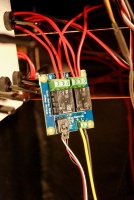
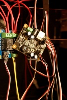
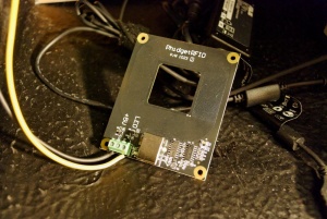
The relay board has 2 Single Pole Double Throw (SPDT) units and is used to control the pump (on/off) and the solenoid valve (trigger/firing). All the servos from the arm are connected to the black advanced servo controller, in addition is the power for the relay switch drawn from one of the servo outputs. Lastly, the temporary RFID board conveniently include two digital outputs, perfect to control the relays (true/false). The RFID part of the board is not used in this project.
The override allow for manual control over the pump and valve if the relay controller is disconnected or not used. Both relays default to Normally Open (NO) configuration.
Programming
Application
I wrote a new Java application based on some code I had used previously for a Room Control project. In addition to the regular Java libraries, I used the Phidgets API to talk to the relay and control the servo controller.
The app is built and compiled in the Eclipse SDK.
Remote Control
The final idea includes the ability to remotely control the arm. The Java API for the Phidget servo controller allow for remote calls via IP. The only difference is to use a different "signature" a.k.a number of arguments when calling the servo Open() function, and to specify the IP address and port for main machine where the controller and network service is running.
One of the cool things about the API is that it accepts connections from multiple sources, a.k.a. two users can control the robot arm, i.e. one controls the movement of the arm and the other triggers the firing button.
Live Video Streaming
As for the streaming software, it had to be something with zero buffering, low-delay, and compression overhead. I tried the free Windows Media Encoder and Expression Encoder kits to stream via the MMS protocol, but I couldn't get the buffering/delay below 4 seconds.
Turned out only a more proprietary application/protocol could deliver the real time stream I wanted. Unreal Streaming Technologies develop three components for streaming video; Live Server for each camera, Media Server to aggregate all the incoming streams, and the Media Player to receive the streaming either directly from the Live Server or via the Media Server. Free but with some limitations on number of streams and codecs.
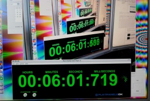
The real time input lag is no more than 300 ms, which is very respectable. The delay is slightly more over a local network, but not much.
References
- Lynxmotion Picture Gallery - Shows most of their robots
- Lynxmotion Videos - like to stonehedge and chess videos
- Building Lynxmotion BRAT
- Lynxmotion owner finds success with robot kits - Interview at the end
- Modified Lynxmotion J5 build thread
- What sonar system(s) are you using?
- David Cook Robot Room
