T-Rex 250 Setup
This shows the setup of my T-Rex 250 and the experience I've had learning and experimenting with the build. Please visit RC Heli Wiki for an excellent resource regarding helicopter terms and concepts.
Follow this guide to-to-bottom, get a good mechanical setup before setting up the electronics. A great companion is Bob White a.k.a Finless' videos.
Prerequisites
Follow the manual to setup the basic build and then use these steps to do the finer adjustments. The virtue of this setup should be to make the most adjustments as precise as possible. Any sloppy or oblique leveling will have an adverse affect later on.
Blades
Grip
The right amount grip on the blades can be tested by gently hitting the leading edge of the blades with your finger they should fold back about 45 degrees. If they fold all the way back and bind with the blade grip then they're too loose. The blades will swing back and forth in FFF due to airspeed differences between the advancing and retreating blades. This is normal but having a little bit of friction helps to dampen it and make a smoother flight. However you need to make sure both blades blade bolts are tightened the same amount.
Balance
Correct blade balancing and blade weight will reduce vibration and stabilize the helicopter. It's an essential part of the setup. Make sure the surface you're performing the balancing is perfectly level.
Balancing the blades on a T-Rex 250 is not really necessary, but it's a good practice to check the blades anyway.
A good way to balance the blades consist of a two part method:
- Find the center of mass (or center of gravity) of each blade by applying trim tape to the end of the lighter blade
- Then, use a blade balancer to apply trim tape to center of mass mark on the ligher blade until they're level
The video linked below shows the procedure.
Tracking
Bad tracking is caused by one blade tracking a little higher or lower than the other. By marking each blade with contrasting tape it's possible to see which one need adjustment.
The tracking can be fixed by lengthen or shortening the link holding the main rotor spindle. Only do adjustment by one whole turn at a time. If a half turn is needed, don't turn the link a half a turn but go to the link one step down on the Bell Hiller level arms. These arms will have more range and will give the rotor spindle more gradual control.
Servos
Try to weight balance the helicopter putting the tail servo tilting to the left and the elevator servo pointing right. This will improve the center of gravity (CG).
A build tip to avoid having the servo arm hit the main gear on the left side, is to swap the aileron and pitch servos. Then the servo arm on the left side will not have a steep angle against the holes in the main gear. When swapped, the arm will point in the same direction as the main gear rotation. If it hits, it won't get stuck.
The elevator servo should be installed on the inside of the frame, with the main mounts on the inside and the body sticking outwards.
The linkage ball and link rod fit is usually pretty tight and light force is needed to move the link rod. When moving the link rod around the ball, the movement should require just a tiny bit of force and move almost freely. It's to free when the link rod dangles, it should move free enough that a slight air blow would move the rod and instantly stop. Use a appropriately sized ball link re-sizer tool to do a few revolutions between each try to find the perfect fit.
Receiver
AR6100e receiver setup (RECEIVER - Device):
- THRO - ESC
- AILE - Right cyclic servo
- ELE - Rear cyclic servo
- RUD - Gyro (3-wires plug)
- GEAR - Gyro (1 wire plug - gain)
- AUX1 - Left cyclic servo
Other receivers will have different layout.
Radio
Create a new profile for the helicopter and reset all the settings. Make sure there are zero trim, zero sub-trim, revo-mix turned off, 50/50/50% swash mix, diagonal pitch and throttle curve, and other settings default or at their suitable values.
Watch the beginning of Finless CCPM setup to get a good start.
When dealing the RC helicopters, always remember to power on the radio first then the receiver and power to the engine, reverse the rutine to disconnect. The helicopter could spin-up unexpectedly if the receiver doesn't have contact with the radio. Low throttle stick and throttle hold is also important before flight.
Head
The head setup should mechanically be as symmetrical and zero-pitched as possible. The radio should have a straight pitch curve (0-50-100) in normal mode before starting the adjustments.
This is only the mechanical build, the tweaking is mentioned below. Install the servos and mount a suitable servo arm 90 degrees to the swashplate. Connect the rods to the swashplate with the length specified in the manual.
Figuring out the correct direction of the swash servos is a two step process. Move the throttle stick slightly up and watch the servos, all three should move collectively up to raise the swashplate, if one servo goes in the opposite dirrection go into the radio setup and reverse the direction of the affected servo. Alternatively if the swashplate is moving down while the stick is moving up, go into the swash mix and invert the pitch value, from positive to negative. Do the same for aileron and elevator.
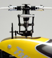
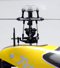
The head is split up in 3 levels, from top-to-bottom; Bell-Hiller/Seesaw mixer level, washout arms level, and the swashplate level (look at the picture below). On zero-pitch the Bell-Hiller/Seesaw and washout is level. That's determined by the lengths of the link-rods connecting to the arms. Both arms should be identical length for each level. The washout arms should be positioned in the middle of the shaft for maximum and minimum pitch travel when moving throttle stick.
If everything seem level, use a digital caliper verify and duplicate the length of related link rods. This will reduce vibrations and tracking issues.
CCPM - Collective Cyclic Pitch Mixing
Final CCPM setup:
- 3 servo 120° degrees apart
- Swash mix (will differ from model-to-model):
- Aileron: -30%
- Elevation: +35%
- Pitch: +40%
- No exponential
- Maximum/Minimum blade pitch: 11.0°
- Aileron/Elevation blade pitch: 6.0°
This is a compact summary of RC Heli Wiki and Bob Finless White videos, please refer to those for details.
The Collective Cyclic Pitch (CCPM) mixing controls the pitch and movement of the rotor and flybar, thus lift pitch (up/down), aileron movement (left/right), and elevation movement (forward/backward). It's called collective because there are 3 servos involved. There are two types of CCPM, mechanical bell crank and electronic mixing. The latter one is used on most helicopters today but requires precision servo setup and radio configuration. The radio is setup to mix, or compute the values, for the 3 servos in order to move the swashplate in the right direction and plane. Be it up-down, left-right, or forward-backward. It's imperative that the head is precisely setup mechanically to get a good CCPM configuration.
First check if the servos are going in the right direction, if one servo goes in the opposite direction, reverse that channel. Alternatively, if you move aileron left, but the swashplate moves right, go into the swash mixing, change the positive aileron percentage to negative value to reverse the movement.
Swash mixing controls the pitch of the blades. A pitch gauge is mounted on the main blades and is used to measure a predetermined pitch against the level flybar. The higher the value, the steeper the pitch. A regular setup usually use collective pitch 10.0° or 11.0° (lift) , higher for more flexibility. The maximum and minimum pitch should never bind and lock the servos. Aileron and elevator pitch is normally 6.0° (navigation).
After the process below is done, everything should be level and swash mixing complete, the movement of the collective pitch to maximum or minimum should keep the swashplate level. But it's not always true if the servos move in different speed or travel range. This issue is called CCPM interaction and can be handled by watching the flybar at aileron and elevator position (side, front) while moving the pitch up and down. Use travel adjust (not sub-trim) to counter the reaction and dial in the appropriate servo travel to keep the swashplate level for the full top to bottom range.
These are my notes when I first set up the head:
- Pitch curve 0-25-50-75-100%, throttle center stick, zero trim, zero subtrim, 50-50-50% swash mix
- Find best horizontal servo arm/horn
- Sub trim to perfection, 100% horizontal arm, center stick
- Add swashplate, use length of rods per manual
- Put on leveling tool, use sub trim to level swashplate to perfection (going away from perfection in #3, but no more than what can be corrected by rod adjustments)
- Test maximum washout travel (up to the beginning of the head) and minimum swashplate travel (down against the shaft lock disk), adjust rods to fit swashplate+washout in the middle of the shaft, e.g. one (or more) turns on all 3 rods up or down, swash should stay level, play around, test maximum throw e.g. low throttle+aileron/elevation
- Adjust flybar-cage rods so that washout and flybar is level, washout floats between swash and flybar-cage, rods should be identical length, alternatively use sub trim on all 3 servos to lower/heighten swashplate (where static rods, e.g. T-Rex 250)
- Seezaw/Benhiller should be level, hold flybar 100% horizontal and measure, adjust length on rods from swashplate to seesaw, identical, nothing special
- Same with blade rods, level, identical length
- CCPM interaction, two steps, turn flybar paddle on 90° to the side of the heli, adjust elevator servo travel on full and low throttle, then flybar paddle straight on heli, adjust aileron servo travel, don't touch pitch servo travel
- Pitch 11.0° positive and negative, adjust swash mix pitch value, if positive and negative blade pitch doesn't match or is different, the washout and/or Seesaw/Benhiller was not 100% horizontal level, readjust from step #7 and forward
- Aileron and elevation 6.0° positive and negative, hard to get absolute, find middle point
Ended up these settings, these are for MY heli, yours will differ:
- Swash mix: 3 Servos, 120degrees, Exp inh., Aile -30%, Elev +35%, Pit. +40%
- Travel adjust: Thro: H100L100, Elev D94U100, Aile L109R103, Rudd L100R100
- Subtrim: Thro 0, Eleve U13, Ail L2, Rudd 0
- Reversing sw: Ch 1Thro Nor, 2Aile Rev, 3Elev Nor, 4Rudd Rev, 5Gear Nor, 6Pit Nor, 7Aux2 Nor
References:
- RC Heli Wiki CCPM Setup
- Bob White CCPM setup videos
- Bob Finless White CCPM 1 video
- Bob Finless White CCPM 2 video
- CCPM interaction
- Jermo's DX7 Setup Video
- UK Heli Log CCPM Swash Leveling
Pitch/Throttle curves
T-Rex 250 curves per manual:
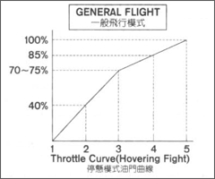
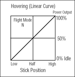
- Throttle Normal mode: 0-40-70-85-100% (now using 0-45-70-85-100)
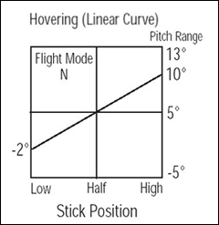
- Pitch Normal mode: 40-X-55-X-100% equals -2°, +X°, +4°, +X°, +11° blade pitch (now using 50-x-65-x-100)
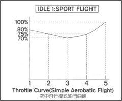
- Throttle Stunt1 / IdleUp 1 mode: 80-75-70-75-100%
- Pitch Stunt1 / Idle-up 1 mode: 0-X-75-X-100% equals -11°, -X°, +5°, +11°
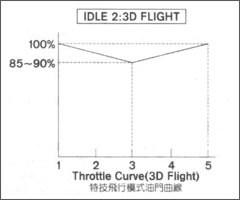
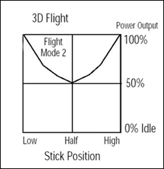
- Throttle Stunt2 / IdleUp 2 mode: 100-X-90-X-100%
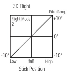
- Pitch Stunt2 / IdleUp 2 mode: 0-25-50-75-100% equals -10, -X°, 0°, +X°, +11°
Throtle curves graphics from the T-Rex 250 manual:
The idea behind pitch and throttle on one stick is to keep a constant headspeed. If the pitch is steep more engine power is required to keep the headspeed revolutions up. This is accomplished by setting up curves on the radio for controlling the pitch and throttle individually. There is usually a 5-point coordinate system to set the percentage at a specific stick position. Many, up to 3, curves can be used for different flight modes; hovering, stunt1/idleup1, and stunt2/idleup2.
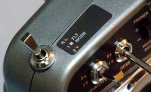
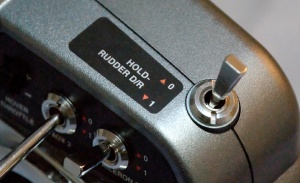
On the radio there's a way to switch between Normal Mode (hovering), Stunt Mode 1 (3D), and Stunt Mode 2 (more power 3D). Stunt mode is also referred to as IdleUp 1 and IdleUp 2, while hovering is called Normal mode. A last mode is Throttle Hold for auto-rotation on engine failure, a second switch is normally used for this. Useful when battery is empty or when a crash is inevitable (less damage).
Normal Mode is used during spin-up and hovering. With the stick down the engine will be off and with 70% up the helicopter should be hovering. These parameters are mainly set-up on the radio by altering the engine throttle and rotor pitch curve.
With Stunt Mode turned on the hovering mode is turned into a flexible mode where the helicopter can perform acrobatics and be flown a up-side-down. Essentially the Normal Mode above 50% is mirrored to the 0-49% section of the stick, but with a negative rotor pitch instead. Look at the picture below to understand the difference between Normal and Stunt.
While setting up the curves, there is an option to enable Exponential. Expo. will smoothen the curve and stick input will have a finer feel, not rough. More stick movement is required to get to the same servo movement. But it's not recommended to keep expo. on as it removes some of the real feel of the helicopter and can hinder progression in flight style.
Normal, hovering mode example (left throttle, right pitch):
Idle Up, 3D stunt mode example (left throttle, right pitch):
The throttle curve dips on the middle because the pitch is close to 0 degrees, thus requiring less power. Higher pitch requires more engine power to keep the headspeed constant.
The manual for the helicopter usually specifies suitable pitch and throttle curves.
Dual Rates
Dual Rates, as the name suggests, can be used to setup two different servo ranges to limit the maximum throw, or travel. This lowers the sensitivity and can be used to lower the sensitivity of the helicopter in flight (but requires more stick movement).
If the the dual rate is set to 80%, full stick input will move the servo arm 80% of the maximum range. Making dual rates useful for new users and hovering.
Tail
Gyro
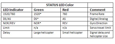
GP750 settings (move rudder stick to left for Green and right for Red):
- Pulse frame rate: 1520us - Green
- Servo type: DS (Digital Servo) - Green
- Servo direction: Reverse - Red
- Servo travel adjustment: Limit set with rudder stick up to max but no binding
- Heli type/delay: Small heli - Green - Delay: 0 (center rudder stick)
The gyro is a device connected between the receiver and the rudder servo, it will stabilize the tail by counter the torque reaction of the main rotor. There are two types, heading hold mode continuously tries to hold the tip of the helicopter at a constant angle, while the other mode, rate mode, dampens any external push to the tail. The former is preferred for normal hovering and acrobatics, while the second is mostly used for scale models.
On the AR6100e receiver the 3 wire plug from the gyro is connected to the RUD-channel and the single gain wire to the GEAR-channel.
Don't move the heli or touch the transmitter sticks when powering on the receiver and gyro. A green light will indicate heading hold mode and red rate mode (GP750).
Setup
Setup:
- Round servo head (less flex)
- 5 mm from servo center
- Gyro Gain: 63% (19% real heading hold gain)
The gyro is connected to the receiver by two plugs. One for the rudder input and one for gain. Gyro gain is used to control how much the gyro tries to control the tail or hold authority and is measured in percentages. The range 0-49% is called rate mode (also called normal mode) and the tail will not automatically bounce back to the original position if it has been pushed by an external force, but rather dampen the movement. While the upper 51-100% range is called heading hold mode (also referred to as AHTCS) and will try to keep the front of the helicopter at a constant angle/heading regardless of external forces. Rudder stick input will notify the gyro and the gyro will then try as hard as it can to rotate, or move the tail, in the direction of the input. Dialing in the gyro gain is essential to get a stable tail.
The intermittent range (0-50% and 50-100%) is used to fine tune the tail gain. If the tail wags back and forth the gain amount has to be reduced and if the heading isn't holding (pirouetting) the gain has to be increased.
Note that the gain wire is electronically connected like any regular servo and if the channel is reversed so will the rates. On most radios, the gyro mode can be setup at specific rates for different flight modes.
There are two ways to set gyro gain, either via the gyro menu or set the channel end points, a.k.a maximum/minimum travel range or adjustment. The former is preferred.
To find the true gyro gain use these equations:
- When using end points/travel adjustment: (End point value) / 1.44
- Or when using the (preferred) gyro sens menu: (Gyro value in radio - 50) * 1.44
A good default start value is around 32% gyro gain (72% in radio gyro mode). It's important to not use any sub-trim on the rudder and adjust the link rod instead, this will leave the gyro in command.
These are my notes when I first setup the tail:
- Zero sub trim, 50% gyro gain, no travel adjustments
- Find best horizontal servo arm
- Adjust link rod length for tail output shaft to be in middle of travel when center stick/servo
- Program gyro, set servo type, frame rate, reverse/normal (to be tested during first flight), servo maximum travel limit, helicopter type and delay
- On spektrum/jr, configure GEAR-channel to GYRO
- Go into Gyro Sense menu, adjust gyro percentage to 63%, which is 19% real gyro gain
- When heli is stationary and in heading hold mode, the servo will not reset position to center when stick is released, this is normal
Guides:
- RC Heli Wiki Controlling Gyro Gain
- Need Help Setting up 401 on a Spektrum AR6100 and DX6i
- Bob Finless White Gyro 101
ESC - Electronic Speed Controller
The default RCE-BL15X settings:
- Brake: Disabled
- Electronic Timing: Medium timing
- Battery Protection: High cutoff voltage protection
- Aircraft: Helicopter 1 Soft Start, no governor mode
- Throttle response speed: Quick speed
- Battery eliminator circuit (BEC): 6.0V for receiver/servos
Although the ESC is pre-programmed from factory, do re-program it to make sure the settings are at the supposed values. It eliminates any issues that might be introduced during manufacturing or storage.
Higher BEC voltage will give the servos more torque and reaction time. For specific servos requiring 5.0V or 5.5V (e.g. Futaba), use a servo step down voltage regulator.
Battery
What makes a good battery pack good is the ability to hold voltage under load. When you start to fly aggresively, some battery pack will drop more voltage than other, resulting in bogging of head speed. A good battery pack will have minimal voltage drop during heavy load, resulting in more punch and consistent speed.
Deans Connector
There are two main types of battery connectors, Deans and JST. Bullet plugs are used between the motor and speed controller. The JST connector is known have a low amperage rating (10-15A) and after awhile the surface will oxidize, eventually resulting in more resistance and heat. It could in extreme cases cause flight problems or unexpected twitching during peak load (e.g. full throttle and pitch).
File:Helicopter deans connectors.jpg
Replacing the plug with Deans connectors will improve the contact surface area and thus rating (50-75A). They're also easier to connect and disconnect, compared to JST.
Charging
Charger
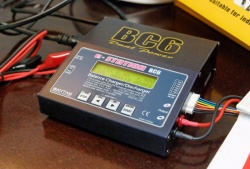
Bantam BC6 charger:
I found that the Bantam BC6 would fit my needs and provide the quality I like. There are a few clones based on this charger, showing the reputation the manufacturer has for making chargers (Hint: good). Bantam is a Korean company.
The Bantam BC6 can charge 3x 2S, 2x 3S, and 1x 6S batteries. Maximum power output is 5.0A. Maximum discharging is 0.5A (due to limited heat dissipation).
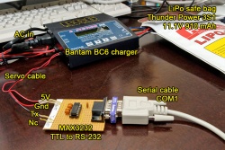
It's possible to hook the charger up to a computer to monitor and record the charging sessions. Bantam offers a suitable Serial-to-USB cable and software, but it's also possible to make your own cable and use an 3rd-party application called LogView.
Charging in series
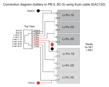
If the charger supports charging 6S1 batteries it's possible to connect two 3S1 batteries in series and charge them both at the same time. The essential part is the connect the main leads together, normally via a Y-Deans cable. Then connect the individual balancing wires from both batteries to the chargers cell balancing outputs, e.g. from battery #1 connect balancing wires to 1-3 on the charger. Next, split the balancing wire 3 from the charger so that it connects to the last cell on battery #1 and first cell on battery #2. Lastly connect the remaining 4-6 balancing wires to the charger. Also, connect the main Deans cable the to separate positive/negative output on the charger.
Remember: Always triple check your setup. Dealing with LiPo and possible short-circuit could be dangerous.
Part list:
- 1x EAC120-1 Bantam E-STATION 8-pin cable for BC6/PB6
- 1x AM-8022 CMAX Y Deans for series connection
- 2x 3s Balancer Female Connector
LiPo
Always use a quality charger when dealing with LiPo batteries. The batteries pack a lot of energy and requires special attention.
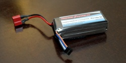
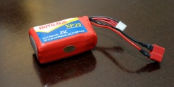
A normal LiPo battery for helis run in series of 2 or 3 cells. Combining cells in series means higher voltage and greater discharge capacity. To charge a LiPo battery, a balancing charger is recommended to properly charge each cell individually. Similarly charging only via the main leads will cause the capacity be unevenly distributed across the cells and could cause damage to the battery and in extreme cases explosive fires.
The continuous discharge capacity of a battery is specified in 'C's, where 1C is equal the capacity of the battery, e.g. a TP 910 mAh 11.1v 20C LiPo battery can handle a discharge of 20C * 860 mA, 17200 mA or 17.2 A continuous. Some batteries also specify the peak, or burst, discharge capacity, e.g 40C, but this is only for short periods of time.
When charging a LiPo, most batteries can only be charged at 1C or less, e.g 910 mAh, or 0.9 A and lower. Some batteries can also be fast charged but only when specified in the manual/label.
The voltage can be calculated by multiplying 3.7V by the number of cells, e.g. 2 series equals 7.4V or 3 series equals 11.1V. Some chargers can detect if the wrong voltage/series is picked before starting the charging.
If the voltage of any individual cell is under 3.0V, the battery is considered dead and should not be attempted to be charged. The battery might be rescued by doing short burst to pump the voltage up and slowly charge it at 0.1 A.
Always remember to disconnect the battery from the heli once done, else the servos will drain the remaining power and damage/weaken the battery cells.
Best practice:
- Charge at 1C or less, where 1C is the capacity of the battery, e.g. charge at 0.8 for a 800 mAh LiPo battery
- Use a good balancing charger, once all the cells are exactly 4.20V, the current flow should stop
- Disconnect the battery charging leads before unplugging the leads from the charger, prevents shorts
- Use a LiPo safety bag and never leave the room during the charging process
References:
NiMH
Nickel Metal Hydride batteries has to be charged slowly and normally doesn't have balancing between cells. Current is forced through the battery and the voltage can fluctuate, thus cannot be used to determine when a battery is full. A NiMH battery be properly charged by setting a timer or temperature sensor.
A normal NiMH charger will put C/10 Amps of current into the battery, e.g. a 1500 mAh (1C) battery will be charged at maximum 150 mA (0.15A) for 15 hours. Modern cells have an oxygen recycling catalyst which prevents damage on overcharge, but this circuit can only keep up if the charge rate is C/10. This method does not require an end-of-charge sensor or timer, although it's good practice to use one.
When a battery is full or begin to overcharge the voltage will drop slightly, a good charger can detect this change and stop the flow of current. The temperature will also increase, which is another method to detect full charge.
Memory effect can occur when a battery is repeatedly only partially discharged. The maximum capacity will decrease, but can be reversed by cycling the battery (discharge-charge). The discharge voltage should not be under 1.0V, e.g. a 8 AA cell 9.6V battery should not drop lower than 8.0V. Use this method to determine discharge voltage to cycle a battery.
Best practices:
- Charge at C/10 Amps, e.g. 1000 mAh (1C) NiMH battery should be charge at 0.1A for 10 hours, fully charged cell voltage is around 1.4V
- Cycling could be done by discharging at light load 0.5A down to 1.0V per cell, e.g. 8.0V for a 8 cell 9.6V battery, then charged at normal C/10 rate
- Use a proper charger with either a timer, temperature sensor, or end-voltage sensitivity sensor.
References:
Final Setup
Photo gallery of the final T-Rex 250 build. Not the greatest lighting, but looks good.
