Difference between revisions of "Eee PC Research"
| Line 12: | Line 12: | ||
* [http://www.intel.com/products/chipsets/910gml/index.htm Intel 910GML Express northbridge chipset with GMA900 graphics processor] | * [http://www.intel.com/products/chipsets/910gml/index.htm Intel 910GML Express northbridge chipset with GMA900 graphics processor] | ||
* [http://support.intel.com/support/chipsets/imst/ Intel 82801FBM ICH6-M I/O southbridge] | * [http://support.intel.com/support/chipsets/imst/ Intel 82801FBM ICH6-M I/O southbridge] | ||
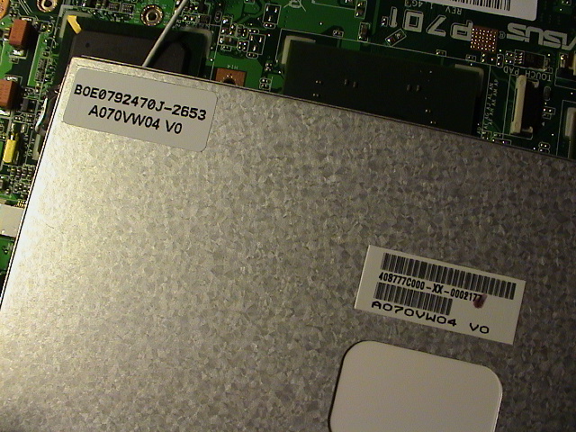
* [http://www.auo.com/auoDEV/products.php?sec=carPortable&func=items&items_id=5 AU Optronics A070VW04 7" widescreen display] | * [http://www.auo.com/auoDEV/products.php?sec=carPortable&func=items&items_id=5 AU Optronics A070VW04 7" widescreen display] [[Image:Eee lcd modelnumber.jpg]] | ||
* Atheros AR5BXB63 wireless adapter | * Atheros AR5BXB63 wireless adapter | ||
* Atheros L2 10/100 Mbit ethernet | * Atheros L2 10/100 Mbit ethernet | ||
Revision as of 15:31, 24 February 2008
I've put together a pack with pictures of my Eee 701 4G showing detailed pictures of the motherboard. Both scans and close-up mosaic pictures of the motherboard are available. Download the picture package.


Specifications
Devices:
- Intel Celeron M 900 MHz 353 ULV 512k processor [1]
- Intel 910GML Express northbridge chipset with GMA900 graphics processor
- Intel 82801FBM ICH6-M I/O southbridge
- AU Optronics A070VW04 7" widescreen display
- Atheros AR5BXB63 wireless adapter
- Atheros L2 10/100 Mbit ethernet
- Silicon Motion SM223 flash controller with Hynix/Intel/Samsung NAND flash chips
- Optional Conexant 56K modem
- ENE UB6225 SD card reader
- Asus 5200 mAh 4 cell 2S2P (2 cells in series and 2 cells in parallel) battery
- Realtek ALC662 audio
- ICS 9LPR426A timing control hub for processor
- ENE KB3310 embedded system controller

Dimensions:
- Width: 22.5 cm
- Depth: 16.5 cm
- Height: 2.1 to 3.5 cm
- Weight: 920 grams
Accessories
Accessories:
- Logitech V470 White Bluetooth mouse
Other suitable accessories:
- Logitech VX Nano mouse
- Microsoft Bluetooth Notebook 5000 / 4000 mouse
- LG GSA-E50L Slim DVD writer
Linux Hardware Output
Output [2]:
00:00.0 Host bridge: Intel Corporation Mobile 915GM/PM/GMS/910GML Express Processor to DRAM Controller (rev 04)
00:02.0 VGA compatible controller: Intel Corporation Mobile 915GM/GMS/910GML Express Graphics Controller (rev 04)
00:02.1 Display controller: Intel Corporation Mobile 915GM/GMS/910GML Express Graphics Controller (rev 04)
00:1b.0 Audio device: Intel Corporation 82801FB/FBM/FR/FW/FRW (ICH6 Family) High Definition Audio Controller (rev 04)
00:1c.0 PCI bridge: Intel Corporation 82801FB/FBM/FR/FW/FRW (ICH6 Family) PCI Express Port 1 (rev 04)
00:1c.1 PCI bridge: Intel Corporation 82801FB/FBM/FR/FW/FRW (ICH6 Family) PCI Express Port 2 (rev 04)
00:1c.2 PCI bridge: Intel Corporation 82801FB/FBM/FR/FW/FRW (ICH6 Family) PCI Express Port 3 (rev 04)
00:1d.0 USB Controller: Intel Corporation 82801FB/FBM/FR/FW/FRW (ICH6 Family) USB UHCI #1 (rev 04)
00:1d.1 USB Controller: Intel Corporation 82801FB/FBM/FR/FW/FRW (ICH6 Family) USB UHCI #2 (rev 04)
00:1d.2 USB Controller: Intel Corporation 82801FB/FBM/FR/FW/FRW (ICH6 Family) USB UHCI #3 (rev 04)
00:1d.3 USB Controller: Intel Corporation 82801FB/FBM/FR/FW/FRW (ICH6 Family) USB UHCI #4 (rev 04)
00:1d.7 USB Controller: Intel Corporation 82801FB/FBM/FR/FW/FRW (ICH6 Family) USB2 EHCI Controller (rev 04)
00:1e.0 PCI bridge: Intel Corporation 82801 Mobile PCI Bridge (rev d4)
00:1f.0 ISA bridge: Intel Corporation 82801FBM (ICH6M) LPC Interface Bridge (rev 04)
00:1f.2 IDE interface: Intel Corporation 82801FBM (ICH6M) SATA Controller (rev 04)
00:1f.3 SMBus: Intel Corporation 82801FB/FBM/FR/FW/FRW (ICH6 Family) SMBus Controller (rev 04)
01:00.0 Ethernet controller: Atheros Communications, Inc. AR5007EG 802.11 b/g Wireless PCI Express Adapter (rev 01)
03:00.0 Ethernet controller: Atheros Technology Corp. L2 100 Mbit Ethernet Adapter (rev a0)
Chips and Connections
A simple diagram showing the major chips and connections on the motherboard.
Top:

Bottom:

Power and Signals
The diagrams below shows power, ground, and signals that's useful when modifying the Eee. All of the points are verified and confirmed working.
Top:

Bottom:

Solid State Drive
The solid state drive on the Eee is powered by a Silicon Motion SM223 CF flash card controller and 4x NAND flash chips from various manufacturers.
NAND flash found:
- Hynix 8Gbit HY27UG088G5M
- Intel 8Gbit 29F08G08CANB2 (found on mine)

BIOS Chip
For a little while there was confusion how the BIOS was stored. Speculation about parts of the SSD could be used for the BIOS, integrated chipset BIOS, or a unknown IC-chip.
Turns out the BIOS chip was covered by a adhesive label and the part number is Winbond 25X40VSIG. It features a 8-pin 512K serial flash.

Update BIOS
The easiest way to update or downgrade the BIOS:
- Download the BIOS zip-archive
- Extract the '.ROM'-file to a USB flash drive
- Rename the '.ROM'-file to '701.ROM' for Eee PC 4G 701
- Reboot the Eee PC and press ALT+F2 during the first POST-screen
- A black screen with the text 'Intel(r))915GM/...' will appear and the process will begin automatically
- Press the POWER-button after the update is finish as described
Clear BIOS
There are two pads in the expansion bay labeled CLRTC, aka Clear Real Time Clock RAM, for clearing the CMOS settings. By shorting these two pads the settings are erased. Up-on booting a 'CMOS Settings Wrong'-prompt will appear and press either F1 for the setup or F2 to load defaults.

Datasheets
- Intel 910GML northbridge chipset with integrated GMA900
- Intel 82801FBM ICH6-M I/O controller hub southbridge
- Intel Celeron M 90 nm processor
- ICS 9LPR426A Low power programmable timing control hub of P4 processors
- AU Optronics A070VW04 7" monitor
- ENE KB3920 embedded controller
References
- Eee PC 701 detailed information
- USB hub, bluetooth and SD reader internal upgrade
- Notebookreview Eee PC Tweaks and Pictures
- Eee PC Hardware FAQ Wiki
- Power consumption USB devices
- Mac OS X on a flash drive
- Eee PC i alles hender
- Asus Eee PC Exclusive Inside Look
- Will Solid State Drive be replaceable?
- Official Asus EEE forum
- Bios 8804 not fully working
- Request: PPL picture / Solved: 900 Mhz under Linux - Module
- Russian Eee 700 review
- 8804 bios poll for XP
- Connecting to GPRS via bluetooth/phone
- Eee 8G 994 MHz overclock
- Mini PCI Express Bus Description
- Eee PC 4G Surf without door memory upgrade
- Hot 8 GB Eee PC secret and pictures
- Internal 1.8" hard drive