Eee PC Internal Upgrades
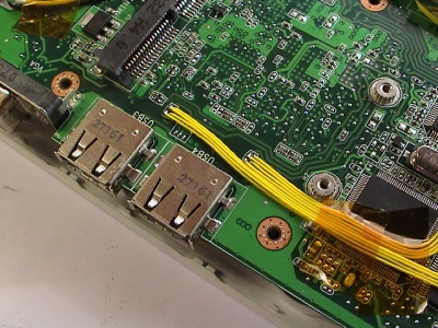
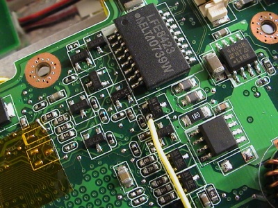
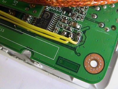
To install devices internally, more USB-connections are needed. I hooked into one of the regular USB-ports and routed the D+/D- signals from the southbridge/controller to a 4 port USB-hub. To make the port I hooked into work again, one of the 4 ports is connected back to the USB-port (Hub-to-USB-port and USB-port-to-HUB). This allows for total of 6 internal USB devices.
There are several points on the motherboard where power can be draw, for both 3.3v and 5v devices. Ground is universal and allows for short runs.
USB hub
I installed 2 hubs to get enough ports and load balancing the bandwidth. Having two storage devices on the same upstream connection is not a good idea speed-wise, therefore I put one on each hub (flash drive and card reader).
The reason I choose to hook into the USB-port and leave the spare Mini-PCIe USB connection alone is that I want to:
- Be able to use Mini-PCIe cards based on USB later.
- Disable the USB-ports in BIOS and disable all the new USB devices.
- Not having to deal with the webcam or wifi disabled in the BIOS affecting the USB hookup (unconfirmed if USB is also disabled).
More information about USB hubs over at Wikipedia.
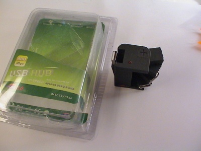
For the type of hub, I went for as small as I could find. The one I found had four rotating USB connections and one upstream connection sticking out from its side. Also a power-LED and external power connector.
It goes under various names, here are a few I found:
- Korea rotating USB hub
- Synapsis flexible hub
- And just " USB 2.0 Mini Rotating Hub"
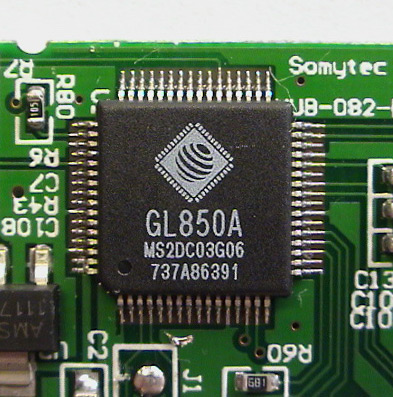
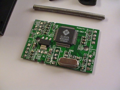
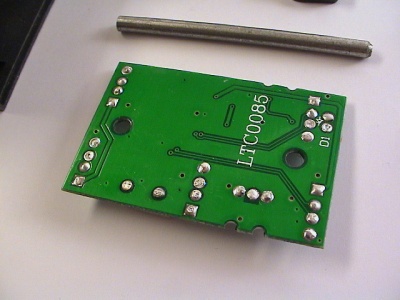
There's also a model with integrated SD card reader. Mine features a Genesys Logic GL850A USB 2.0 chip. The chip runs off 3.3v but I couldn't find a easy way to connect 3.3v directly.
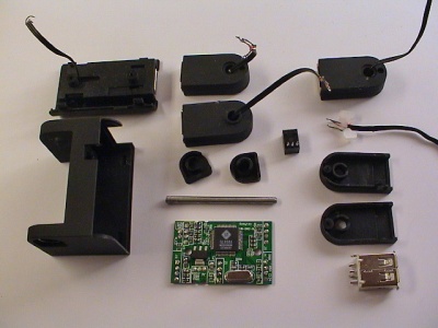
After cracking the case open, I stripped all the unnecessary parts from the circuit board like the LED and external power connector.
Top and bottom:
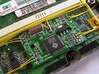
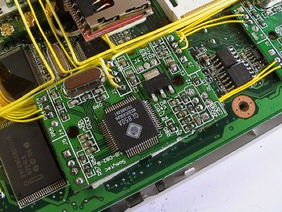
The position of the first hub is directly under the touch pad, next to the memory slot. It fits nicely between two SMD chips and it's not touching the memory socket or covering the microphone hole. Placing it in the middle of the Eee motherboard allows for short data signal wires to the devices.
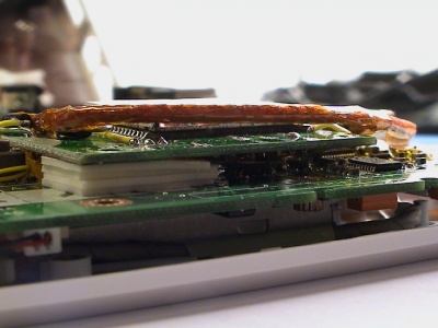
The second hub is covering the SSD NAND flash chips. The underside of the all devices is insulated by electronic tape to avoid possible shorts.
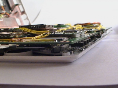
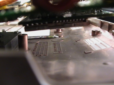
The total height is still low enough to not touch the chassis.
I hooked into the two USB ports on the right-side of the Eee to provide the data signals to the hubs. One of the four ports on each hub is routed back to the onboard USB ports. Essentially moving the USB port over from the motherboard to the USB hub.
Overview:
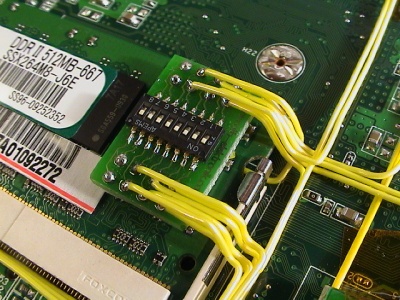
Power is routed from one of the 5v points and through the switch board. Ground is connected to the nearest point.
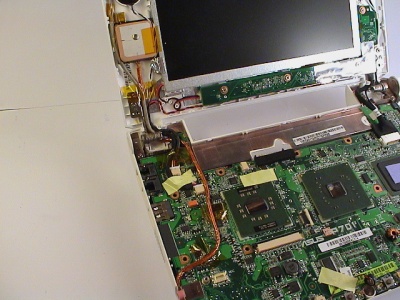
GPS with antenna
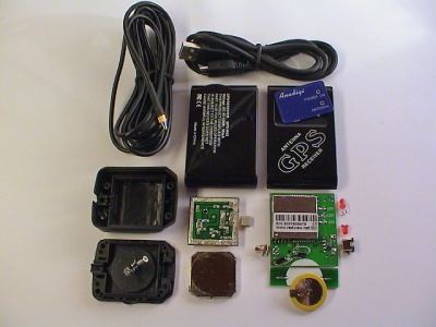
Wouldn't it be cool to have a Eee PC with a integrated GPS unit? Yes! I certainly thought so. Doing some research, I found a DIY kit on Ebay for a decent price. The bulk kit included a GPS unit, antenna with 3 meter cable and mmcx connector, USB cable, plastic case, and two screws. Suitable to be permanently installed in a boat or car.
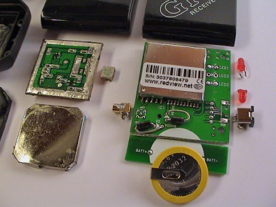
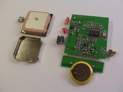
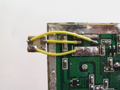
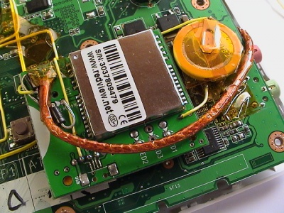
The GPS board itself was quite big and I had to strip it down as much as I could. Removing the LEDS and two connectors was easy, getting the board shorter was a bit harder. The 3.6v standby battery could easily be connected off the board, and cutting the side of the board freed up some valuable dead space.
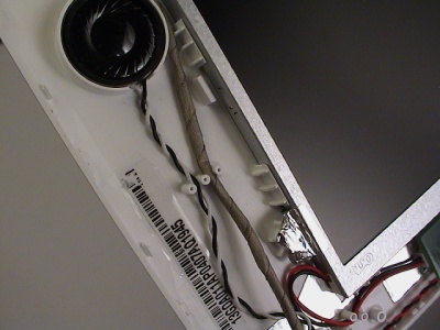
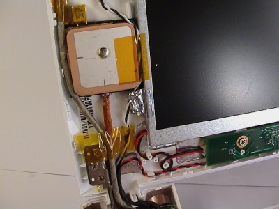
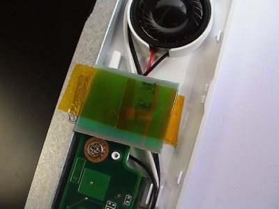
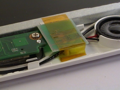
The antenna was the most critical part and had to be fitted outside the shielded Eee chassis. Before ordering the kit I was hoping it would fit in the display, and guess what, it just did by a small margin. The crystal on the underside had to be moved to the side of the main antenna body, and if all is good the RF characteristic won't suffer to much because of that.
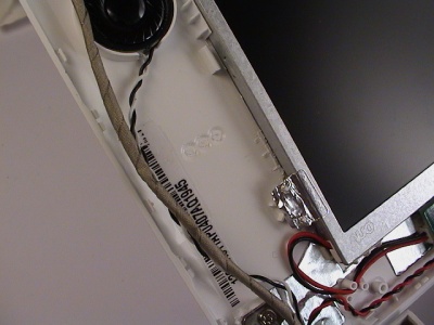
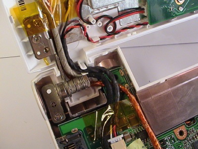
To fit the antenna next to the display, I had to cut away 3 stubs holding the cables in place and a placeholder for the display unit. None of these stubs are voiding the integrity of the display, it all fits and holds together as stock.
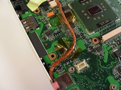
I stripped the outer insulation of the RG-58 coaxial cable and replaced it with Kaptop electronic tape. That made it less rigid and easier to work.
Routing the webcam and speaker wires to make space was pretty easy, lots of slack. I fitted the coax cable first, then soldered the core and shielding to the antenna.
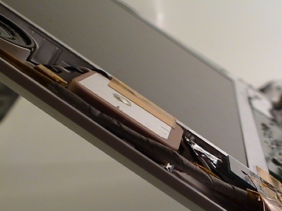
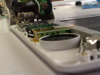
After some more re-adjustments and re-positioning the wires, it turned out quite good I think. The webcam wire placed between the locking mechanism and antenna is not squeezed as it might seem. The antenna unit is flush to the display and the front panel clicks into place perfectly.
The placement for the main unit needed to go through a few trails and errors before figuring out the only space large enough to house the unit was over the ethernet controller, next to the audio and amplifier chip.
It is a tight fit when closed, but there is still space lef over the unit. Though not much. It's powered by 5v.
After everything is finally installed, it looks like this.
Bluetooth
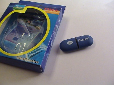
Somehow Asus decided to not include Bluetooth in the final Eee revision. Previous prototypes showed a clear Bluetooth icon on the keyboard, but all production machines lack the icon and stock Bluetooth support.
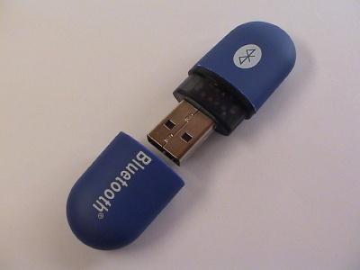
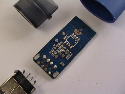
Bluetooth adapters have always been small and recently newer models is just the size of the USB connector. I decided to find a cheap no-name adapter and found a egg shaped one on Ebay.
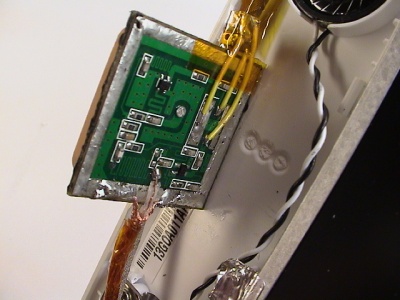
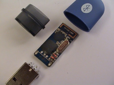
Opening the adapter has to be one of the easiest I've done so far. The casing is just held together by a center piece and the circuit board in the middle. Luckly, the adapter was easy to run off 3.3v. I removed the LED to save another 20-30 mA.
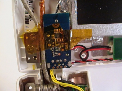
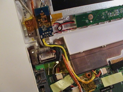
After mounting the GPS antenna, the only place left to mount the adapter is in the bottom-left side of the display. All other places the Bluetooth antenna would be blocked or the reception degraded. The wires could be routed through the same dip in the motherboard as the fan wires.
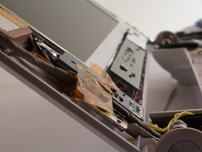
As with the GPS, the adapter is flush to the display and will not protrude with the front panel in place.
Card reader
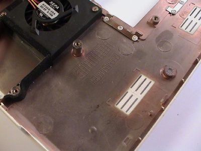
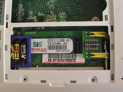
It would be great if I could have a internal storage space that I could replace easily to a higher capacity or take with me if I wanted to. In the expansion bay there is a gap between the memory socket and the bottom casing. It is normally blocked on one side with a piece of black foam.
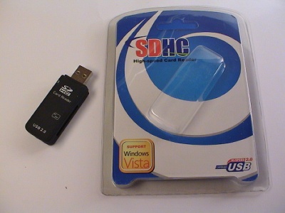
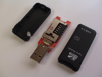
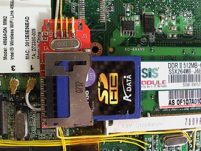
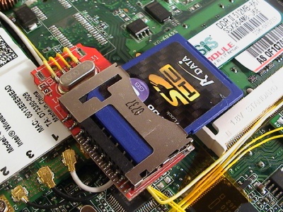
Removing the foam allows for a SD card to just fit in-between. On the inside, there is space between the memory socket and the Wifi adapter for a small USB card reader. Trying both straight-angled and side-angled card readers, only the side-angled card reader fitted properly and even then it had to be stripped down.
The adapter supports USB 2.0 and SDHC cards.
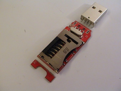
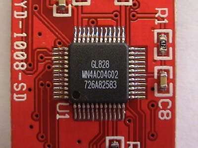
Stripping the USB connector and cutting of the dead space on the end made the adapter smaller. Removing the unnecessary LED also conserves some precious batter power, 20-30 mA. The card reader uses a chip from the same vendor as the USB hub, Genesys Logic GL828.
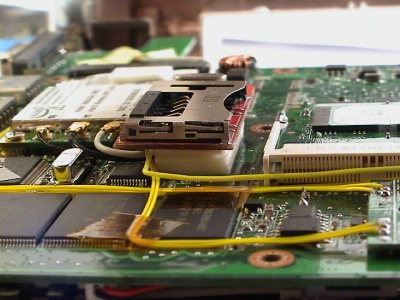
Mounting the adapter at the right height was crucial. Because of the tight fit, the adapter had to have some margin to tilt and move.
The best way seem to pad the bottom of the adapter at the right height using doubled-sided adhesive foam-strips. When closing the case, the bottom of the chassis would press the adapter downwards and hold it at the appropriate height.
As this picture shows, the adapter will touch the Wifi adapter and tilt slightly towards the memory socket.
Flash drive
The internal 4 GB SSD-drive is great and all, but it's limited and I wanted to dual-boot Linux and Windows. Preferable each OS on its own standalone drive.
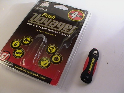
After research for a fast USB flash drive with good read and write transfer rate, the Corsair Voyager GT series seem to hold the trophy. With a staggering stated rates of 34 MB/s read and 25 MB/s write speed, which can be proven in practical use for once.
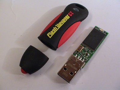
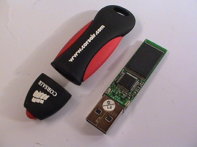
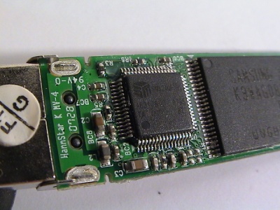
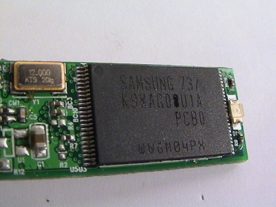
One of the secrets for the fast speeds might have some basis in the flash controller used, Silicon Motion SM324, coupled with the fastest SLC NAND flash chips available from Samsung. The flash controller is actually from the same vendor as the on-board SSD-drive controller.
A future project I want to explore is to figure out if it's possible to de-solder the Voyager NAND flash chips and replace the SSD-drive chips. On paper the SM223 controller should support the Samsung chips out-of-the-box.
I went for the Voyager GT 4 GB model and it should be enough for a OS install. For file storage, I will use the card reader coupled with a large and relatively slower SDHC card.
It's amazing how much can fit on such a tiny piece of PCB-board. The flash controller is a Silicon Motion SM324 hook up to a pair of Samsung K9WAG08U1A SLC NAND flash chips.
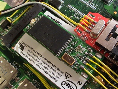
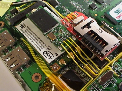
After fitting all the other devices, it began to get cramped, but I found space for the flash drive on top of the Wifi adapter. If I'm lucky I can fit another one next to the current one.
The height is just short of the card reader, though the case start to curve where the flash drive is placed.
Power switch
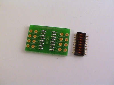
Mouting all these devices internally meant that it wouldn't be easy to completely turn off the devices, although most of them use very little to no power when idle. Instead of hoping they wouldn't use power, I decided to install a switch between power sources and the devices. The DIL switches can be turned on or off from the expansion bay.
The switch had to be small and fit inside the memory expansion bay. After finding perfect dip-switch, I searched for a suitable board to mount it on. Roth manufactures a lot of different prototyping boards, and one of which can be broken into pieces and used to mount SO16 IC chips.
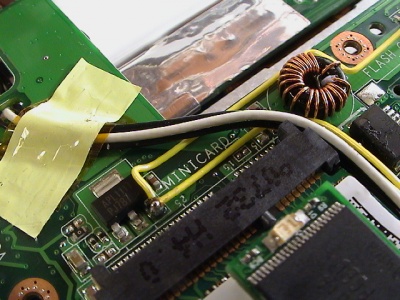
The power sources can easily be found by probing the board using a multimeter. I use one of the already known spots for 3.3v and 5v and probed the board with the multimeter set to continuity, with the Eee power off. This allowed my to find other spots for known good power sources.
Three spots used for 5v shown below. In the last picture, the middle is ground.
Another idea I had was to hook the power for the on-board chips to the chips, allowing for even better power savings. But after probing the board and looking at the chips, I deemed it to be risky and some of the chips have multiple power inputs.
- Integrated devices: Webcam, Wifi PCIe adapter, SD card reader, Sound card, Atheros eithernet, Wifi Mini-PCIe adapter
Wifi
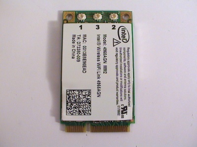
The Wifi-card on the Eee is only 802.11b/g, not the latest draft-N. The card is can be easily replaced by removing two screws and unmounting the card from the Mini-PCI Express socket.
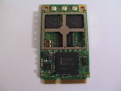
After searching around I found a Intel 4965agn 802.11a/b/g/n Mini-PCIe card for a decent price.
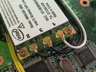
Since 802.11n uses MIMO and spatial multiplexing for better performance and range, it requires from 2 to 4 antennas dependin on the number of transceivers installed.
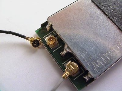
I had a dead Nintendo Wii which happened to use the same antenna connector as the Intel card. The connector is named Hirose U.FL.
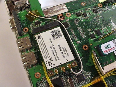
Replacing the AzureWare card the new Intel card was done in a swoop. The new antenna coax cable diameter was a bit smaller and the connector height was lower. Don't know hope it would compare individually to the stock Eee antennas.
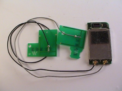
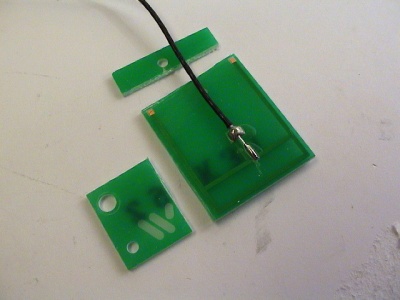
As for the antenna, the element was etched on a PCB board with the cable soldered to the center. I stripped much of the dead space to make it fit inside the right side of the display.
The two antennas already in the Eee was mounted with a horizontal polarization. Considering the 802.11n is precoding and postcoding the signal to split the signal over multiple antennas, I decided to mount the with the same polarization and as far from the other antennas as possible.
I had to strip a short length of the coax cable.
It's as flush as the GPS and Bluetooth adapter.
FM transmitter
Modem
The modem port on the Eee is stuffed with a piece of black foam and not used. The modem is not installed on any Eee machine but the internal connection points are still there. The modem card connected via a MDC v1.5 connection, and 12 pin header for the card and the 2 pin header to connect to the RJ-11 jack is still in place on all current 4G motherboards.
Asus is still providing the Windows driver for the Conexant 56K modem on their download site, look for Modem_XP.zip
The modem card can be found on various Dell, Acer, and Sony laptops. On Ebay the Conexant card can be found under these model numbers:
- Conexant 56K Modem RD02-D110
- M5804 (Dell part number)
Other Possible Upgrades
- USB relay power switch
- New keyboard (non-taiwanese) [1]
- CPU/GPU/Chipset voltage mod
- Silicon Motion NAND flash replacement
- Modemport - Wifi antenna, additional ethernet port
- Modemport as a switch - remove to turn off, plug in to power
- Disable the fan to conserve power
- USB touch-screen overlay
- Copperplate with thermal tape better cooling
References
- Internal USB gadgets on miniPCIe connector
- tnkgrl USB research
- RFID Windows log-on
- Asus EEE News, Mods, and Hacks
- 802.11n Wifi Modification
- Modding Eee 701 with internal bluetooth / Engadget
- Keyboard light mod
- Eee PC USB Hub + Bluetooth + 4 GB flash - Chinese
- Eee PC USB Hub + Bluetooth - Chinese
- Modify generic 12v car adapter to supply 9.5v
- Eee + Hub + 2x 16 GB Corsair Voyager
