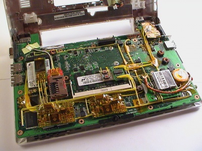
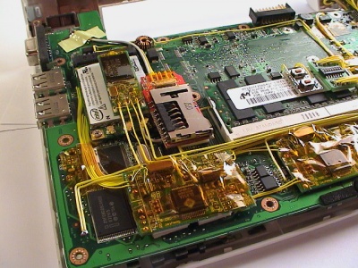
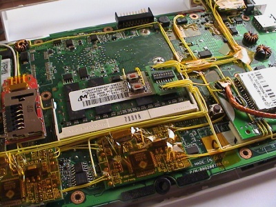
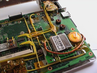
Eee PC Internal Upgrades
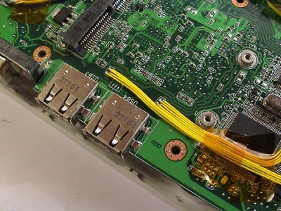
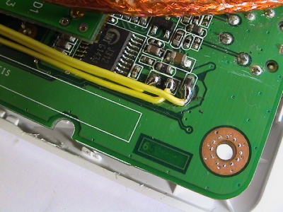
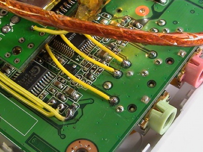
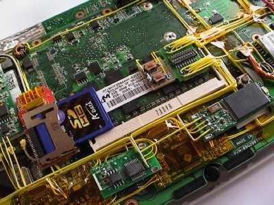
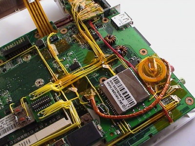
To install devices internally, more USB-connections are needed. I hooked into one of the regular USB-ports and routed the D+/D- signals from the southbridge/controller to a 4 port USB-hub. To make the port I hooked into work again, one of the 4 ports is connected back to the USB-port (Hub-to-USB-port and USB-port-to-HUB). This allows for total of 6 internal USB devices.
There are several points on the motherboard where power can be draw, for both 3.3v and 5v devices. Ground is universal and allows for short runs. A diagram over the points can be found on the research page.
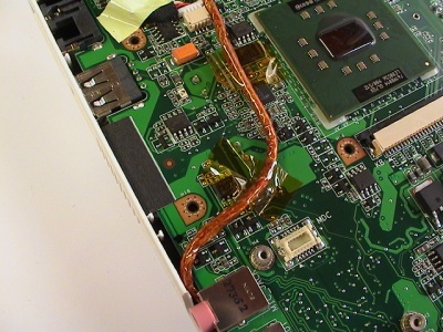
The signal wires thickness is 30 AWG and 24 AWG for the power and ground wires. The wire type is called wire wrap and used for prototyping and repair work. Mine is Tefzel insulated and made by Habia Cable. To cover up and prevent shorts I used 3M Kapton tape.
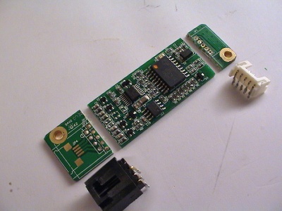
USB hub
I installed 2 hubs to get enough ports and load balancing the bandwidth. Having two storage devices on the same upstream connection is not a good idea speed-wise, therefore I put one on each hub (flash drive and card reader).
The reason I choose to hook into the USB-port and leave the spare Mini-PCIe USB connection alone is that I want to:
- Be able to use Mini-PCIe cards based on USB later.
- Disable the USB-ports in BIOS and disable all the new USB devices.
- Not having to deal with the webcam or wifi disabled in the BIOS affecting the USB hookup (unconfirmed if USB is also disabled).
More information about USB hubs over at Wikipedia.
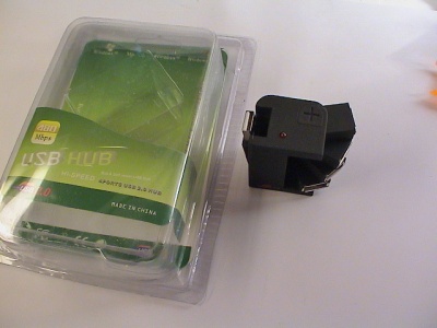
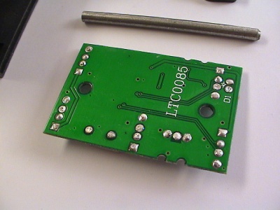
For the type of hub, I went for as small as I could find. The one I found had four rotating USB connections and one upstream connection sticking out from its side. Also a power-LED and external power connector.
It goes under various names, here are a few I found:
- Korea rotating USB hub
- Synapsis flexible hub
- And just " USB 2.0 Mini Rotating Hub"
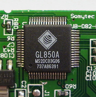
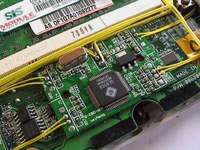
There's also a model with integrated SD card reader. Mine features a Genesys Logic GL850A USB 2.0 chip. The chip runs off 3.3v but I couldn't find a easy way to connect 3.3v directly.
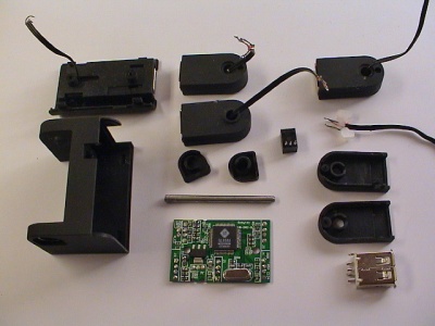
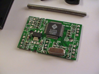
After cracking the case open, I stripped all the unnecessary parts from the circuit board like the LED and external power connector.
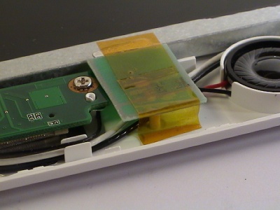
Top and bottom:
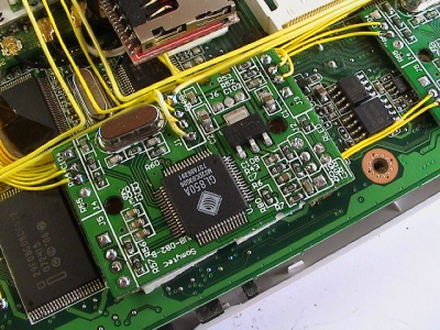
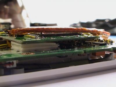
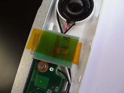
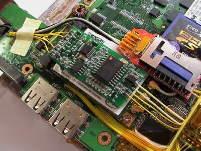
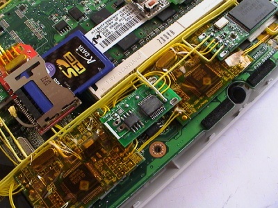
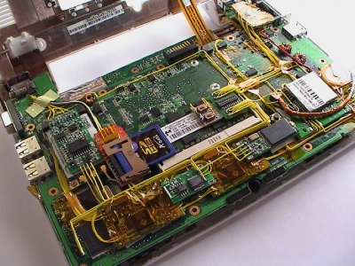
The position of the first hub is directly under the touch pad, next to the memory slot. It fits nicely between two SMD chips and it's not touching the memory socket or covering the microphone hole. Placing it in the middle of the Eee motherboard allows for short data signal wires to the devices.
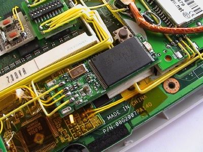
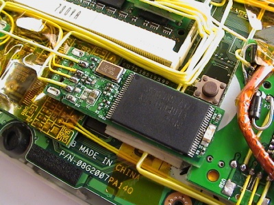
The second hub is covering the SSD NAND flash chips. The underside of the all devices is insulated by electronic tape to avoid possible shorts.
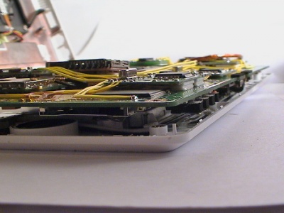
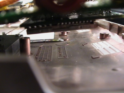
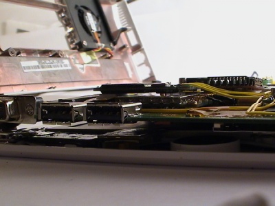
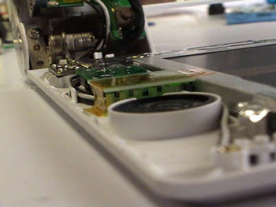
The total height is still low enough to not touch the chassis.
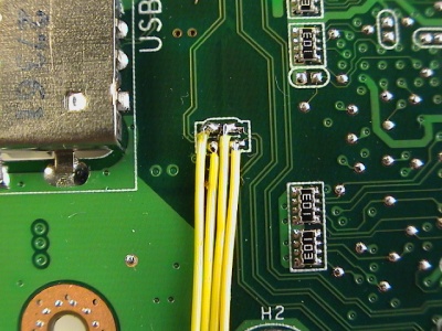
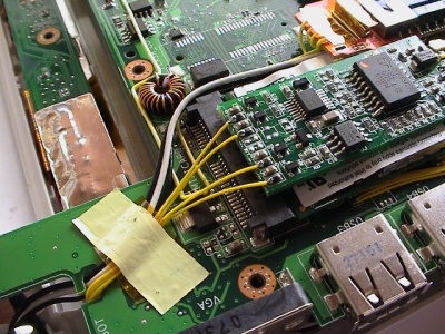
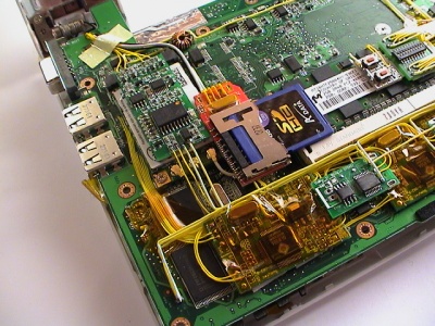
I hooked into the two USB ports on the right-side of the Eee to provide the data signals to the hubs. One of the four ports on each hub is routed back to the onboard USB ports. Essentially moving the USB port over from the motherboard to the USB hub.
On the picture to the right, the two wires on the right-side is connected to the onboard chipset traces and the wires goes to the USB hub. The two other wires on the left-side comes from the USB hub and goes back to the USB connector on the right-side of the Eee PC.
Power is routed from one of the 5v points and through the switch board. Ground is connected to the nearest point.
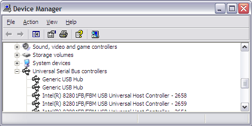
Windows XP recognized the hubs and all the attached devices.
GPS with antenna
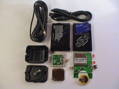
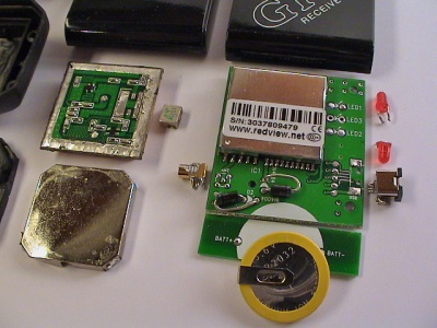
Wouldn't it be cool to have a Eee PC with a integrated GPS unit? Yes! I certainly thought so. Doing some research, I found a GPS DIY kit on Ebay GPS-R02-DIY for a decent price. The bulk kit included a GPS unit based on a NemeriX chipset, antenna with 3 meter cable with mmcx connector, driver min CD-R, USB cable, plastic case, and two screws. Suitable to be permanently installed in a boat or car.
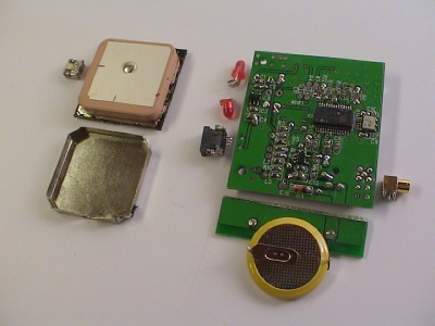
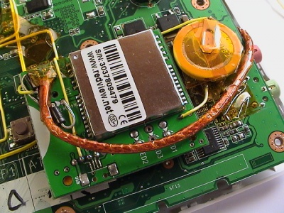
The GPS board itself was quite big and I had to strip it down as much as I could. Removing the LEDS and two connectors was easy, getting the board shorter was a bit harder. The 3.6v standby battery could easily be connected off the board, and cutting the side of the board freed up some valuable dead space.
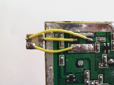
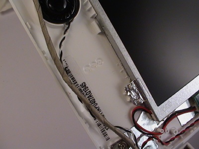
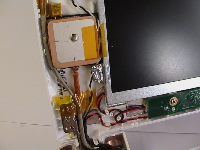
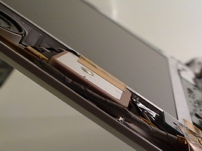
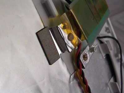
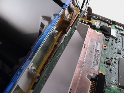
The antenna was the most critical part and had to be fitted outside the shielded Eee chassis. Before ordering the kit I was hoping it would fit in the display, and guess what, it just did by a small margin. The crystal on the underside had to be moved to the side of the main antenna body, and if all is good the RF characteristic won't suffer to much because of that.
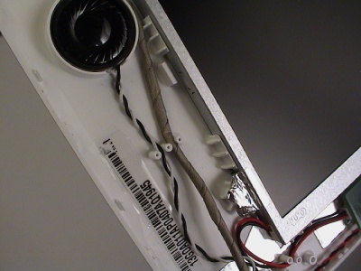
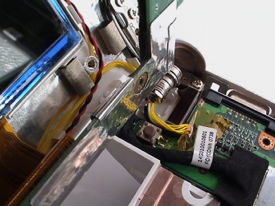
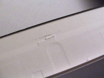
To fit the antenna next to the display, I had to cut away 3 stubs holding the cables in place and a placeholder for the display unit. None of these stubs are voiding the integrity of the display, it all fits and holds together as stock.
I stripped the outer insulation of the RG-58 coaxial cable and replaced it with Kaptop electronic tape. That made it less rigid and easier to work.
Routing the webcam and speaker wires to make space was pretty easy, lots of slack. I fitted the coax cable first, then soldered the core and shielding to the antenna.
After some more re-adjustments and re-positioning the wires, it turned out quite good I think. The webcam wire placed between the locking mechanism and antenna is not squeezed as it might seem. The antenna unit is flush to the display and the front panel clicks into place perfectly.
The placement for the main unit needed to go through a few trails and errors before figuring out the only space large enough to house the unit was over the ethernet controller, next to the audio and amplifier chip.
It is a tight fit when closed, but there is still space lef over the unit. Though not much. It's powered by 5v.
When everything is finally installed, it looks like this.
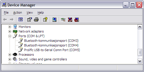
To get the GPS working in Windows XP, I had to install the included driver for the Prolific PL-2303 Serial-to-USB transceiver. The GPS support 16 channels and the clear-text de-facto NMEA standard, which means most GPS mapping programs work with this module.
My unit was mounted on COM5 (Bluetooth occupies the other COM-ports).y
On the mini-CD-R was a GPS tester program to verify the connection.
Datasheets (thanks Simon Stapleton) (mirror):
- Nemerix NJ1030A baseband processor
- Nemerix NJ1006A RF front end
- LEON2 SPARCv8 architecture
- GRMON and other associated tools for LEON
- RV80 GPS Engine Board User Manual
Pin-compatible (or nearly so) GPS modules:
Bluetooth
Somehow Asus decided to not include Bluetooth in the final Eee revision. Previous prototypes showed a clear Bluetooth icon on the keyboard, but all production machines lack the icon and stock Bluetooth support.
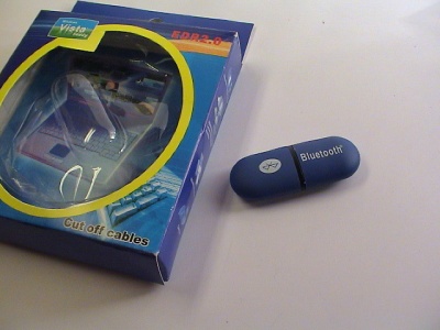
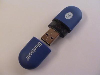
Bluetooth adapters have always been small and recently newer models is just the size of the USB connector. I decided to find a cheap no-name adapter and found a egg shaped one on Ebay.
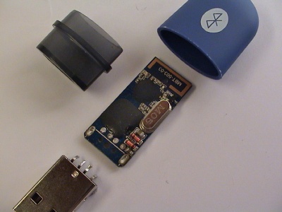
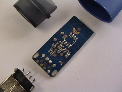
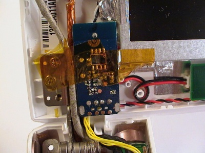
Opening the adapter has to be one of the easiest I've done so far. The casing is just held together by a center piece and the circuit board in the middle. I removed the LED to save another 20-30 mA.
Luckly, the adapter was easy to run off 3.3v. The trick to figure out of the adapter can run off 3.3v is to follow the tracer from the USB connection and down to either a series of resistors (black) or diodes (orange glassy). And checking the voltage on the other side of the components to see if it converts 5v down to exact 3.3v. Also make sure that 5v is not needed on any other component on the adapter. Looking up the datasheet for the IC-chip is also a good idea if it's available.
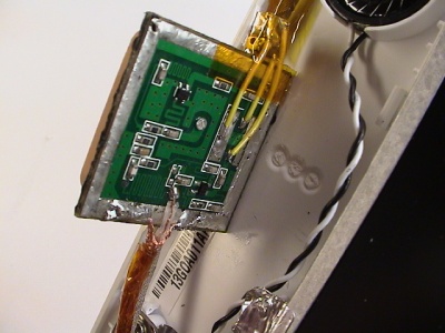
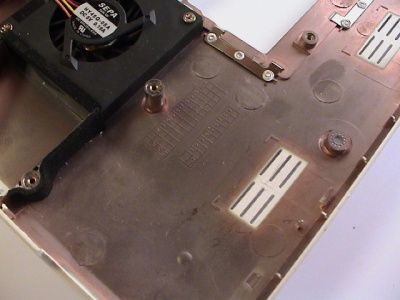
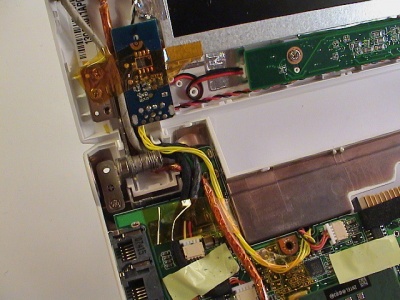
After mounting the GPS antenna, the only place left to mount the adapter is in the bottom-left side of the display. All other places the Bluetooth antenna would be blocked or the reception degraded. The wires could be routed through the same dip in the motherboard as the fan wires.
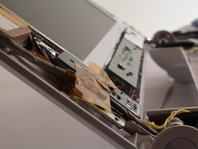
As with the GPS, the adapter is flush to the display and will not protrude with the front panel in place.
In Windows XP the Bluetooth adapter was not automatically installed. And it's probably a good thing because the default Bluetooth drivers are notoriously bad and limited.
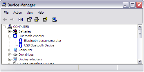
I went a head and found a copy of the latest Widcomm Bluetooth drivers and had to manually patch the btwusb.inf text file to include the vendor and product identification numbers for my adapter. The essential string from the device manager is VID_0E5E&PID_6622. Most Bluetooth devices are manufactured after a default specification and the Widcomm drives can be made to work if the device is not already included.
Card reader
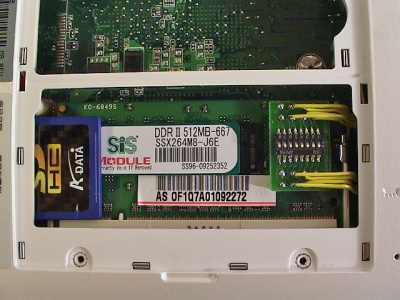
It would be great if I could have a internal storage space that I could replace easily to a higher capacity or take with me if I wanted to. In the expansion bay there is a gap between the memory socket and the bottom casing. It is normally blocked on one side with a piece of black foam.
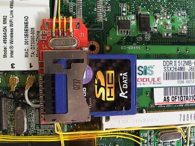
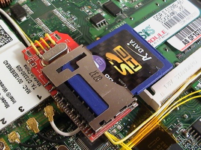
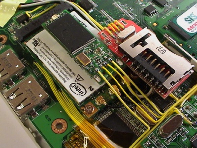
Removing the foam allows for a SD card to just fit in-between. On the inside, there is space between the memory socket and the Wifi adapter for a small USB card reader. Trying both straight-angled and side-angled card readers, only the side-angled card reader fitted properly and even then it had to be stripped down.
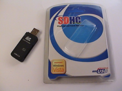
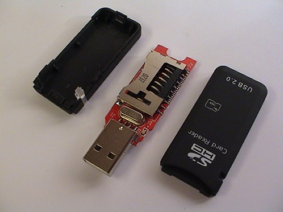
The adapter supports USB 2.0 and SDHC cards. I found it on Ebay and seems to be a generic brand without any model number. This user seems to have them in stock as of writing.
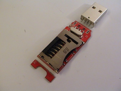
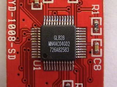
Stripping the USB connector and cutting of the dead space on the end made the adapter smaller. Removing the unnecessary LED also conserves some precious batter power, 20-30 mA. The card reader uses a chip from the same vendor as the USB hub, Genesys Logic GL828.
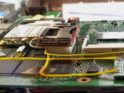
Mounting the adapter at the right height was crucial. Because of the tight fit, the adapter had to have some margin to tilt and move.
The best way seem to pad the bottom of the adapter at the right height using doubled-sided adhesive foam-strips. When closing the case, the bottom of the chassis would press the adapter downwards and hold it at the appropriate height.
As this picture shows, the adapter will touch the Wifi adapter and tilt slightly towards the memory socket.
In Windows XP, no extra driver had to be installed to get it to work, as it was recognized as a mass storage device.
Flash drive
The internal 4 GB SSD-drive is great and all, but it's limited and I wanted to dual-boot Linux and Windows. Preferable each OS on its own standalone drive.
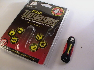
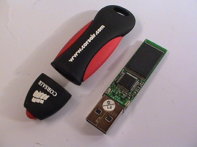
After research for a fast USB flash drive with good read and write transfer rate, the Corsair Voyager GT series seem to hold the trophy. With a staggering stated rates of 34 MB/s read and 25 MB/s write speed, which can be proven in practical use for once.
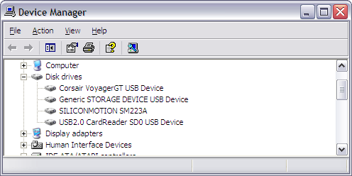
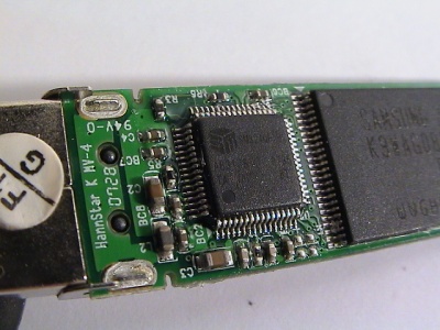
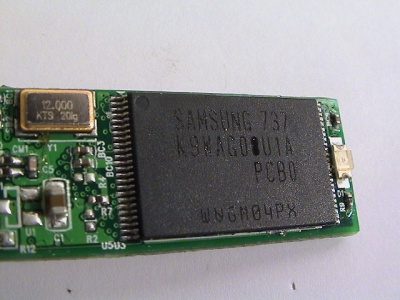
One of the secrets for the fast speeds might have some basis in the flash controller used, Silicon Motion SM324, coupled with the fastest SLC NAND flash chips available from Samsung. The flash controller is actually from the same vendor as the on-board SSD-drive controller.
A future project I want to explore is to figure out if it's possible to de-solder the Voyager NAND flash chips and replace the SSD-drive chips. On paper the SM223 controller should support the Samsung chips out-of-the-box.
I went for the Voyager GT 4 GB model and it should be enough for a OS install. For file storage, I will use the card reader coupled with a large and relatively slower SDHC card.
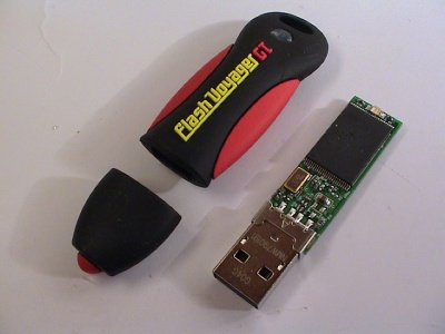
It's amazing how much can fit on such a tiny piece of PCB-board. The flash controller is a Silicon Motion SM324 hook up to a pair of Samsung K9WAG08U1A SLC NAND flash chips.
Old location
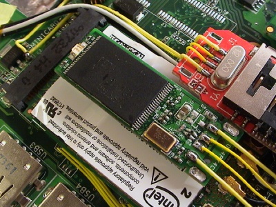
After fitting all the other devices, it began to get cramped, but I found space for the flash drive on top of the Wifi adapter. If I'm lucky I can fit another one next to the current one.
The height is just short of the card reader, though the case start to curve where the flash drive is placed.
New location
When I installed the touch-screen overlay I couldn't find space for the controller and I had to rearrange the flash drive. It's now located between the first USB hub and the GPS module. It's mounted by padded two double-sided foam patches together. The flash drive barely fits as the case curves and narrows at the edge of the motherboard.
The old power, ground, and data signals are used by the touch screen controller.
As for all USB mass storage devices, it works right out-of-the-box. The drive is recognized as Corsair VoyagerGT in the BIOS and is bootable.
Power switch
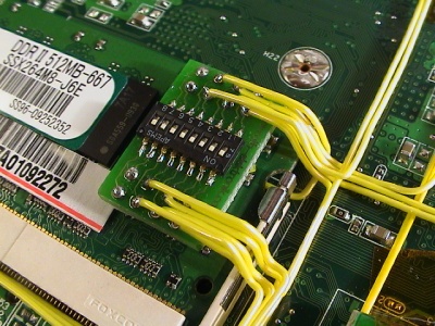
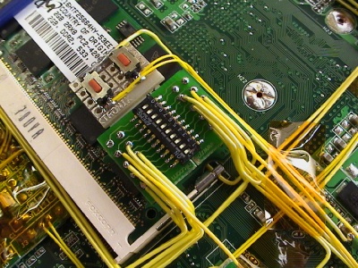
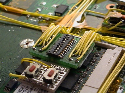
Mounting all these devices internally meant that it wouldn't be easy to completely turn off the devices, although most of them use very little to no power when idle. Instead of hoping they wouldn't use power, I decided to install a switch between power sources and the devices. The DIL switches can be turned on or off from the expansion bay.
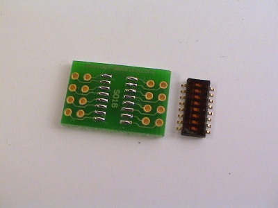
The switch had to be small and fit inside the memory expansion bay. After finding perfect dip-switch, I searched for a suitable board to mount it on. Roth manufactures a lot of different prototyping boards, and one of which can be broken into pieces and used to mount SO16 IC chips.
Old 8 dip-switch
DIP-switch layout:
- USB hub #1
- Bluetooth
- GPS module
- SDHC reader
- USB hub #2
- Flash drive
- FM transmitter power
- FM transmitter audio-enable
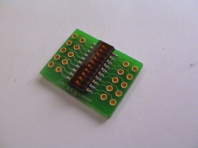
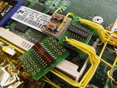
New 10 dip-switch
While installing the touch screen and temperature sensor, I ran out of power switches and had to upgrade the board. I would like to have 12-14 switches, but the maximum on a single board was 10 dip-switches. The width of the prototyping board I had left was to wide and had to be modified.
- USB hub #1
- Bluetooth
- GPS module
- SDHC reader
- USB hub #2
- Touch screen
- FM transmitter power
- FM transmitter audio-disable
- Flash drive
- Temperature sensor
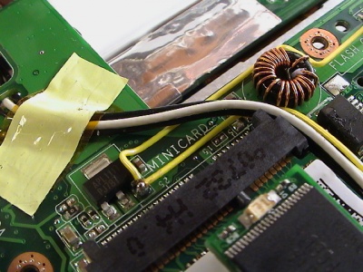
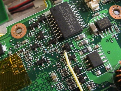
The power sources can easily be found by probing the board using a multimeter. I use one of the already known spots for 3.3v and 5v and probed the board with the multimeter set to continuity, with the Eee power off. This allowed my to find other spots for known good power sources.
Three pictures showing spots for 5v shown belo.
From left-to-right: 5v, ground, 5v.
Another idea I had was to hook the power for the on-board IC-chips, i.e. SD card reader, webcam, ethernet, to the power switch, allowing for even better power savings. But after probing the board and looking at the IC-chips, I deemed it to be too risky and some of the chips have multiple power inputs not just a single point.
- Integrated devices: Webcam, Wifi PCIe adapter, SD card reader, Sound card, Atheros eithernet, Wifi Mini-PCIe adapter
Wifi
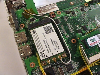
The Wifi-card on the Eee is only 802.11b/g, not the latest draft-N. The card is can be easily replaced by removing two screws and unmounting the card from the Mini-PCI Express socket.
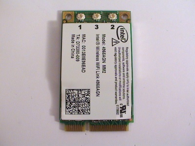
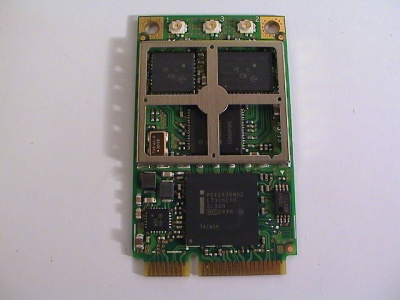
After searching around I found a bulk Intel 4965AGN 802.11a/b/g/n Mini PCI-express card for a decent price.
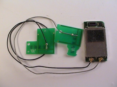
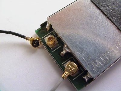
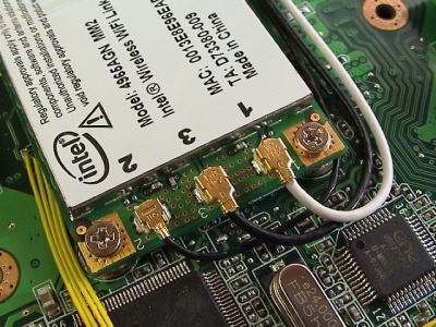
Since 802.11n uses MIMO and spatial multiplexing for better performance and range, it requires from 2 to 4 antennas dependin on the number of transceivers installed.
I had a dead Nintendo Wii which happened to use the same antenna connector as the Intel card. The connector is named Hirose U.FL.
Replacing the AzureWare card the new Intel card was done in a swoop. The new antenna coax cable diameter was a bit smaller and the connector height was lower, but I hope it will perform near or as good as the two other stock Eee antennas. As you can see below, the new antenna is connected to number "2", I going to swap it out and move it to "3" instead. I want the two good antennas first on "1" and "2", and new one on the "3" connector in case the first two connectors are used for 802.11b/g networks.
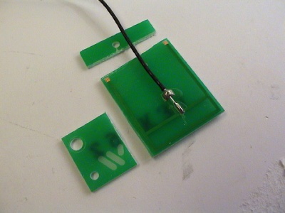
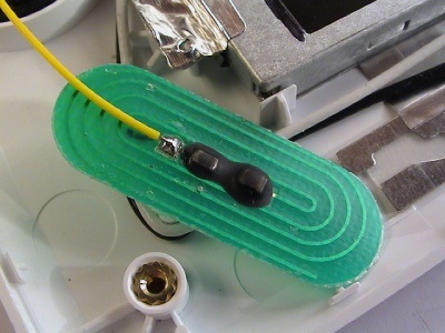
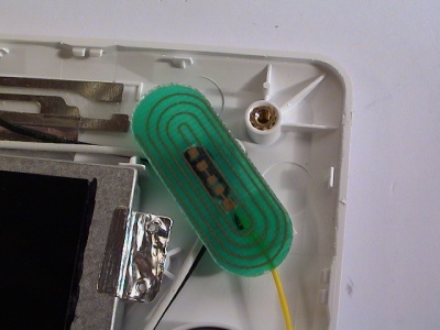
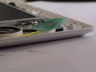
As for the antenna, the element was etched on a PCB board with the cable soldered to the center. I stripped much of the dead space to make it fit inside the right side of the display.
The two antennas already in the Eee was mounted with a horizontal polarization. Considering the 802.11n is precoding and postcoding the signal to split the signal over multiple antennas, I decided to mount the with the same polarization and as far from the other antennas as possible.
I had to strip a short length of the coax cable.
It's as flush as the GPS and Bluetooth adapter.
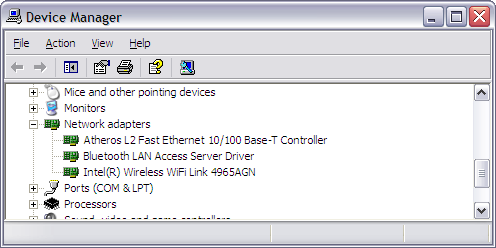
After downloading the latest from Intel's site, extracted the x32-folder and installed the adapter the manual way. Once installed, the default Wireless Network Connection utility found all the nearby wifi-spots.
FM transmitter
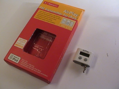
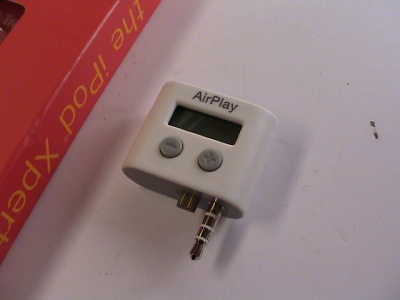
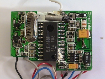
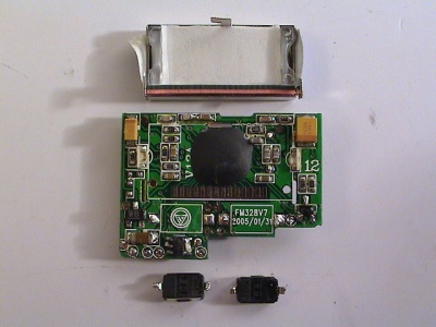
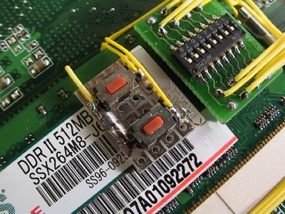
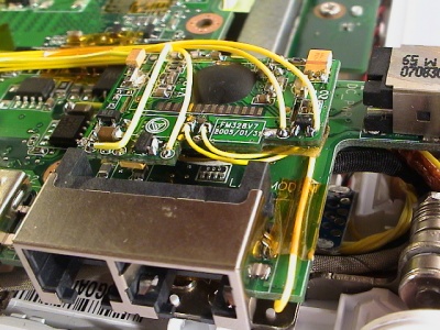
It would be cool to have a ultra-portable computer with a FM transmitter for roadtrips, etc. The smallest transmitter I found was a AirPlay adapter for iPods. It has a regular audio-jack and an additional 4-pin side-plug for power and serial data. The transmitter is not connected to the USB hub and runs off 3.3v. To change frequency I de-soldered the buttons and mounted them on a tiny PCB-board and placed it in the memory expansion bay.
The pinout for the iPod headphone jack can be found on pinouts.ru (on the right-side).
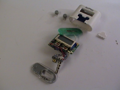
It was quite hard to crack the case and I had to destroy the case to get the board out.
The display is to tune the frequency to transmit on and two buttons to adjust in .5 steps.
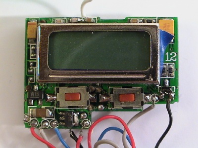
Space is limited and I stripped the display and buttons to make it as low profile as possible.
The installation is done in three steps; antenna, audio input, and buttons.
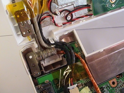
With limited space in the display bezel, the antenna could only be mounted on the right side. Removing the old cable and routing a new multi-strain cable from the left side of the motherboard, under the display, and up on the right side of the display.
It fits perfectly and still some free space for the front panel.
I had to probe the audio-jack on the Eee motherboard to figure out the audio left, right, and ground points. From front-to-back in the middle of the picture, ignore the three wires to the left: audio left, audio right, and audio ground.
The Airplay display had to be removed and frequency changing is done blindly. To be able to adjust the freqency, I had to move the buttons to the expansion bay. I found a piece of prototyping board, mounted the two switches, and soldered two wires from the Airplay board back to the expansion bay where I placed the prototyping board. One side of the switches is ground and the other for plus and minus signal. The frequency is changed up or down when the signal is low (ground).
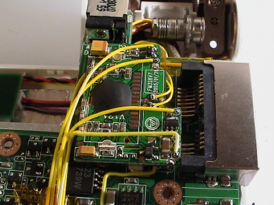
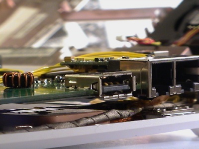
And the main unit could only fit in the empty space between the DC-power and ethernet/modem-jacks. Pretty much a perfect spot.
No problem with height, it might touch the bottom of the case but it's hard to inspect.
Modem
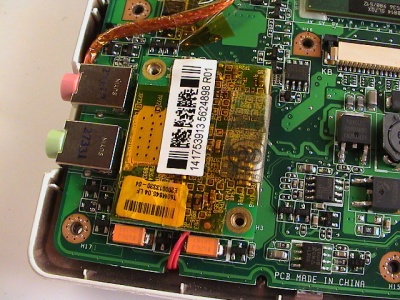
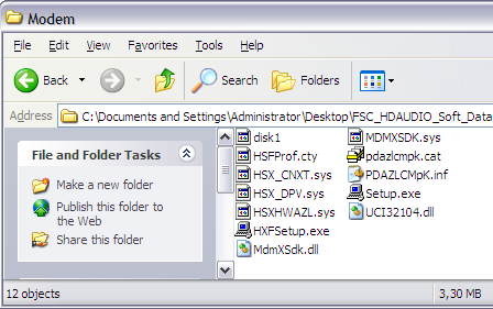
The modem port on the Eee 4G is stuffed with a piece of black foam and not used. The modem is not installed on any Eee machine but the internal connection points are still there and supported in BIOS 8804. The modem card connected via a MDC v1.5 connection and 12-pin header is not removed. There's a internal 2-pin header that is connect to the RJ-11 jack. A wire from the 2-pin header is connected to the MDC card.
Asus was providing the Windows driver for the Conexant 56K modem on their download site, but it's gone now. Although it's possible to hack another Conexant drive to make it work on the Eee (more below).
The modem card can be found on various Dell, Acer, and Sony laptops. On Ebay the Conexant card can be found under these model numbers:
- Conexant 56K Modem RD02-D110
- M5804 (Dell part number)
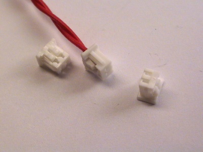
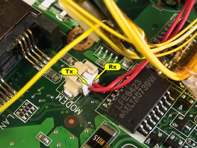
To install the modem, two wires from the internal header has to be run down to the MDC slot. I found a suitable connector and leads with the correct 1.25 mm pitch for the header socket. Although I didn't find a connector for the MDC-side. I had to solder the wires directly onto the back of the connector.
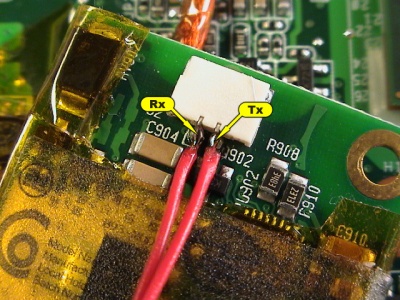
After stripping the wires, I had to figure out which wire was Tx and Rx. The easiest way was to just connect them blindly and test if I could get a connection. Luckly I did on first try, the correct Tx and Rx points are shown below.
This was a pretty easy install. Just hooking up the wires and pressing the modem card onto the MDC header on the motherboard.
And the height shouldn't be a problem since the spot was made to fit a modem card from the get-go.
Notice that only the older 8804 BIOS version has support for the modem, Asus removed the modem functionality on all newer revisions of the BIOS.
To get the modem to install in Windows XP, I had to go through several modem drivers before concluding that every manufacturer made their own cards and drivers to fit a specific laptop series. The reason I guess is to stop people going to the competitors driver download page to get the modem driver.
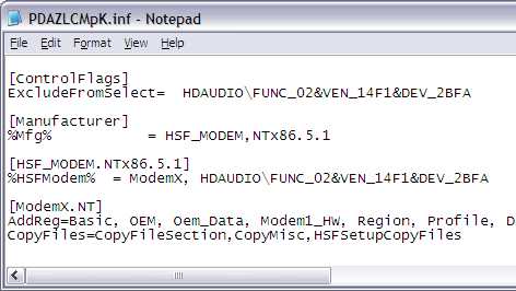
After finding a driver that fitted the description of the RD02-D110, I figured that I had to change the INF-file to make the Windows devices wizard recognize the modem. Fortunately a Fujitsu-Siemens Amilo Xa2528 seems to use the same driver I needed. I hacked/modified the INF-file by removing the string &SUBSYS_14F10001 from the ControlFlags, HSF_MODEM.NTx86.5.1, and Strings-sections. Also make sure that the VEN and DEV variables are the same as in the device manager, e.g 14F1 and 2BFA respectively.
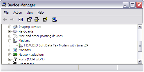
Once modified, open device manager and try to install the modem driver. It should recognize the modem this time and should show up as HDAUDIO Soft Data Fax Modem with SMARTCP.
System memory
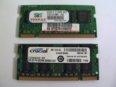
The stock memory on the 4G is one stick of SiS 512 MB SSX264M8-J6E SO-DIMM rated for DDR2 PC2-3200 667 MHz CL5. Contrary to early popular belief, the system memory is limited to 400 MHz and not 800 MHz. The specification in the datasheet for the Intel 910GML chipset states on page 26 the following.
This means that the system performance can be boosted by looking at the latency timings (CL) instead of purely on the frequency speed. All DDR2 modules started out at 400 MHz, making it easy to modules with the best timings. The lower speed modules tend to be higher priced because they're older and harder to get hold of. Find a module with good timings for a reasonable price, the frequency speed is irrelevant.
Another secret about memory modules is that most of the higher speed modules run with a better timings on lower speeds, e.g. a 533 MHz CL4 module will have CL3 latency when running 400 MHz. These settings are stored in a small EEPROM on the module.
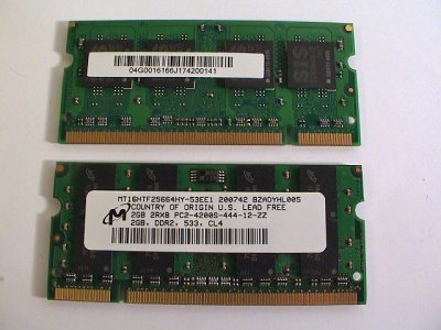
I found a decent Crucial 2 GB CT25664AC53E DDR2 PC2-4200 533 MHz module.
Touch screen
This the first new modification (March 2008) since first leg above. Another Eee user, jkk [1], inspired my to try this modification. The trick is to find a perfectly sized touch screen that matches the dimensions of the LCD on the Eee PC. If it's too large the casing will bulge.
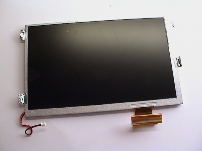
Eee PC AUO A070VW04 LCD monitor dimensions (datasheet):
- Outter dimensions: 164 x 103 x 5.1 mm (w x h x d)
- View area: 154.4 x 94.44 mm (w x h)
- Active area: 152.40 x 91.44 mm (w x h)
The overlay should have a view area large enough to be covered by the bezel and an active area that covers the LCD monitor active area.
The candidates are:
- Unknown no-name 7-inch 4-wire touch screen (no datasheet) - This is the one jkk used - possibly sold by LinITX, unverified, looks the same - [2] [3]
- Outter dimensions: 165 x 105 x 1 mm [4]
- LeadingTouch 4-wire 4W0701AT-G11, alternatively 4W0702AT-G11 - sold on Ebay (kiddshop) - [5] [6]
- Outter dimensions: 168.4 x 105.4 x 1.4 mm
- View area: 157 x 93.4 mm
- Active area: 154.9 x 91.9 mm
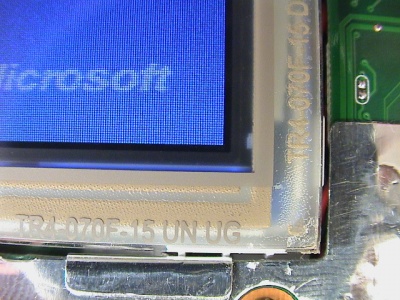
- Liyitec 4-wire TR4-070F-13N-E01 or TR4-070F-15N-A02 - latter sold on Ebay (avoid fido-dido999 reseller of Karpc? [7]) - [8] - Recommended
- Anti-glare layer, non-removable
- Outter dimensions: 164.70 x 103.70 x 1.35 mm
- View area: 157 x 96 mm
- Active area: 153.00 x 92.04 mm
- Xenarc 4-wire TK700-4WUSB (no datasheet) - sold by Karpc video, Dynamixcomputers - [9] [10] bulges
- Hantouch 4-wire H6070A-NCOFB87 / H6070A-NDOFB87 - sold on Ebay (dboluarte, mobileandsolid) - [13] [14] [15] - Big and wide controller - Recommended
- Outter dimensions: 164.6 x 105.6 x 1.35 mm
- View area: 156.4 x 95.44 mm
- Active area: 153 x 92.04 mm
- (Outter dimensions 103.4 x 178.7 x 23.1 mm)
- Unknown 4-wire - sold by CarTFT - [16] pictures
Other companies: Itminc, Gunzeusa
There is a driver called TouchKit for touch screens using the EETI eGalax resistive controller, including the jkk's kit, LeadingTouch, Liyitec, and Karpc kits. As long as the resistive controller board looks similar, the driver should work.
Preparation
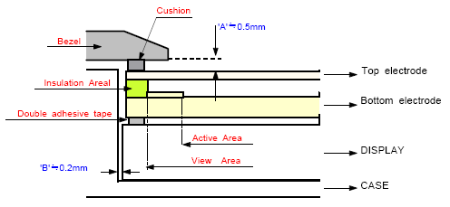
The overlay will add another 1.4 mm to the LCD height and in order to avoid bulging a few modifications has to be made to the monitor and surrounding mount.
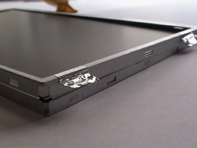
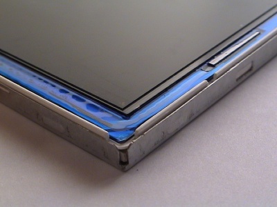
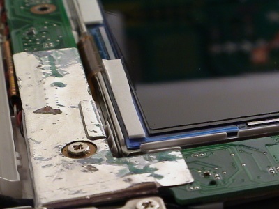
After disassembling the monitor and disconnected the wires, the first thing to remove is the top metal frame. Simply lift the frame off the clips on the sides by carefully prying them using a screwdriver. Removing the frame will free 0.3-4 mm.
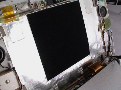
Next, when the monitor was mounted there were four grounding gaskets behind supporting it in addition to a black square blanket. Removing both will free 0.5-7 mm.
Once removed the area where the monitor will be mounted should be just blank foil.
Removing anti-glare filter
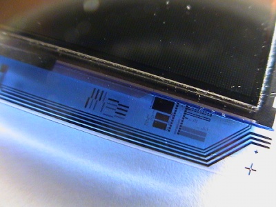
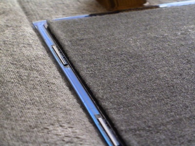
The AU Optronics A070VW04 display has a fine anti-glare layer, aka matte look, applied to it. People have for a long time removed this layer to increase the brightness and overall representation of the produced picture. There are two popular methods, sandpaper and methylene chloride (paint stripper) or water soaking and time [17]. I prefer the latter to get a clean removal.
The touch screen overlay will add another layer of anti-glare as the Eee LCD monitor already has a layer. Kaomoo over at eeeuser.com has managed to gently peel back [18] the anti-glare film off the monitor, pictures [19]. Lumenlab has a good thread over anti-glare film removal.
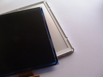
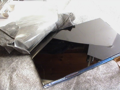
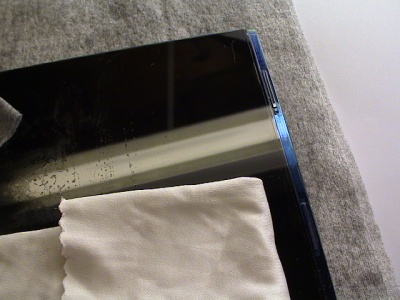
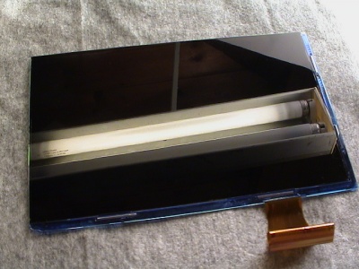
An important thing to note about a LCD display is that there are two transmissive polarizer layers on each side of the glass. The anti-glare is applied on top of the front polarizer. Removing either polarizer will make the display gray or blurry [20]. Remove only the thin top film. The picture to the left has the anti-glare while the other doesn't.
Now, with the top metal frame removed lift out the LCD module from the 'backlight-box'.
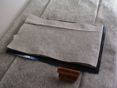
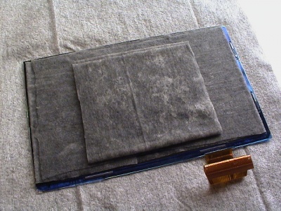
To protect the module from scratches and catch excessive water, place it on a paper towel with fine fibers. Cut out a piece of the paper towel exactly matching the dimensions of the anti-glare filter, maybe exceeding the edge a little.
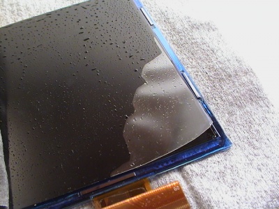
Begin to carefully pore water in the center of the towel, let it soak the water. I used bottled water, it's clean enough. Keep poring water and stop when the paper towel is fully saturation, aka water begins to slip away.
Let the anti-glare filter soak water for 3-4 hours.
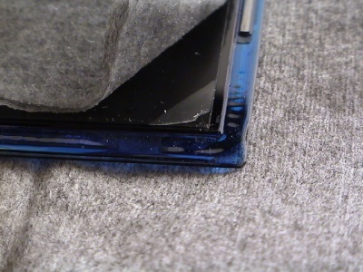
Once soaked, find a sharp high quality razor blade or knife to lift the corner of the anti-glare filter. With the paper towel still in place, begin from either of the corners by holding the blad sideways and carefully flip the blade in a upwards motion to try to lift filter/corner. Remember only the top filter is the anti-glare, they're both glued together and almost impossible to distinguish bare eyed.
Once lifted, watch the edges of the filter as it tends to break up and tear easily if it hits a hard spot that's not properly saturated. Remove the hard spots afterwards.
Clean up any hard spots and remove any glue residue that's left using a micro-fiber cloth and water.
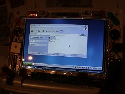
The monitor is incredible crisp and bright without the anti-glare filter. My next laptop or monitor will probably don't have a ag filter, for sure. Pictures show the display with brightness set to 'Very bright' in Eeectl.
Controller board
The touch screen I decided to try was the Liyitec 4-wire TR4-070F-15N-A02 overlay, from fido-dido999 on Ebay. I'm satisfied with it, but I would prefer a finer and removable anti-glare filter, or no anti-glare filter at all. It is a bit to grainy and the anti-glare roughness is harder than the LCD monitor anti-glare filter.
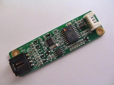
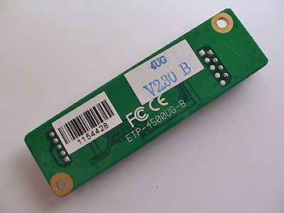
The kit included the Liyitec overlay, touch controller (TouchKit compatible), controller cable, and USB cable. Nothing else.
The controller board is relatively long and to save precious space, cutting the dead ends will make it considerable shorter.
There were no space left in the display casing, and I had to move the flash drive to get enough free room for the controller. It's locationed on top of the Wifi adapter. The board is mounted using a twin layer of double-sided foam tape.
- The power, ground, and data signal pinout as shown on the first picture, right-to-left: 1 (Ground), 2 (5v power), 3 (D+), 4 (D-)
- The overlay wire pinout back-to-front on the right picture: 1 (Y-), 2 (X-), 3 (Y+), 4 (X+)
The overlay wires goes through the same shaft as the wireless antenna coax cables and across the bottom of the screen along the right speaker cable. The thickness of the wires was 30 AWG and I haven't had any problems with them yet.
Overlay
With the grounding gaskets, metal frame, and anti-glare filter now removed, the overlay can be installed. It's a good practice during the entire process to keep a micro-fiber cloth handy to remove any dust and particles on and near the LCD module and overlay.
To keep the overlay in place, I cut three small pads of the foam tape and fitted them in the gap around bottom and right side of the LCD module. The 1 mm height of the foam is just enough to catch the overlay once installed.
To properly align the overlay on top of the LCD module, the display should be turned on to see where the active area begins. The active area dimension is one of two essential parameters to looking for when researching a overlay, the other is the outer dimension.
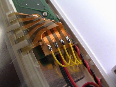
Measure, cut, and strip the wires from the controller and solder them to the overlay flex-cable. Use a glass-fiber pen to scratch the traces.
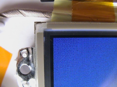
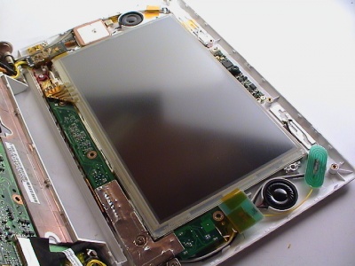
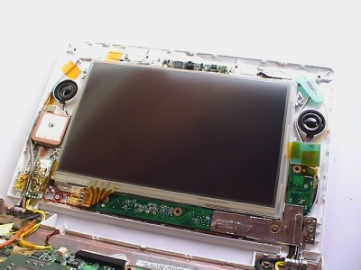
Finally, the touch screen is installed! The overlay is still a bit too high, but the front panel will fit fine and keep the overlay in press.
The flex-cable will block one of the bottom hooks for the front panel and has to be cut.
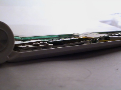
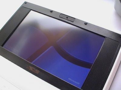
With the front panel assembled , it does not bulge much at all. My front panel is a bit damage by heat and is warped but it still fits fine.
Temperature sensor
The only temperature sensor on the Eee PC is integrated Intel CPU thermal sensor. While it can measure the processor temperature with great accuracy, there is no sensor to measure the ambient air inside the casing.
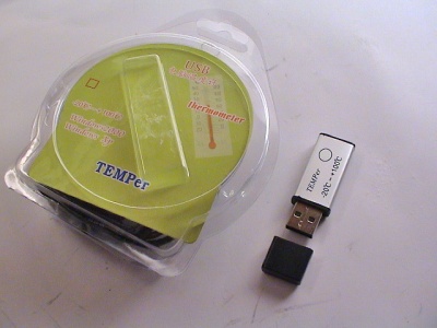
I found a small TEMPer USB thermometer on Ebay that could do the job.
The box and software was in both Chinese and English. The build quality of the PCB and soldering was below standard.
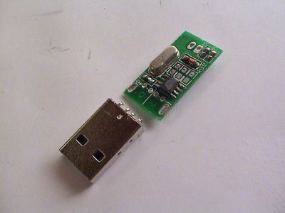
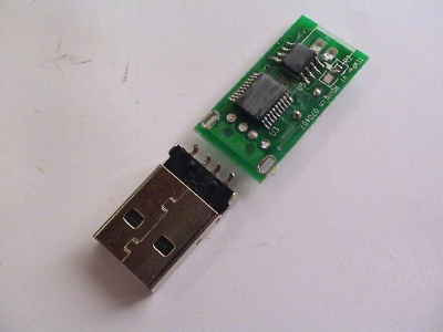
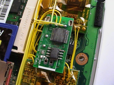
The only free space I could find for the sensor board was between the two USB hubs, with the protruding crystal facing down. The power, ground, and data signals were of course USB pinout standard.
Windows XP did not automatically find a driver but it was included on the mini-CD, together with a monitoring program.
Installation Overview
December 2007
Installing all the devices above except the modem takes some time. I used over a week with a few hours each day to figure out and install the devices. At the current stage it's pretty cramped but I still have two free internal USB ports to do a second flash drive and some other device like a USB thermometer(!).
The first power-up was a success and no major problems has occurred since then. Power seems to be stable and not over-loading the lines. No shorts yet.
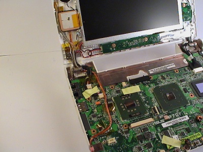
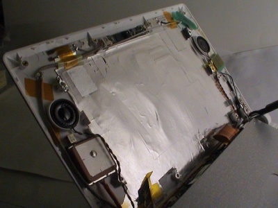
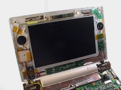
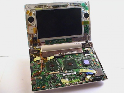
In the picture below the orange GPS antenna is on the left and I moved the BIOS battery from the bottom-side to the top. The Bluetooth wires are routed through the fan wires gap. The display area is populated with the GPS antenna right below the left speaker and the Bluetooth adapter below that. On the right top-side is the FM antenna and the third wireless antenna below the right speaker.
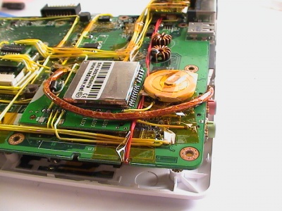
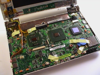
This looks like a mess, but it's actually quite clean and orderly. Starting on the front-left and going round: first USB hub, second USB hub, FM transmitter buttons and power switches in the bay, GPS adapter with standby battery, FM transmitter, draft-N wireless adapter, 4gb flash drive, and SDHC card reader.
The complete computer without the front panels mounted.
March 2008
After the initial upgrade, I wanted to install a touch screen overlay and a thermometer. There were a few different touch screen models too choose from that would fit the Eee PC, but little-to-no detailed information about the manufacturer and specifications. The wires for the overlay is routed underneath the display controller from the left and through the right-hand side hinge.
A few changes had to be made the bottom side of the motherboard, the flash drive had to be moved, power switch was upgraded to 10 switches, and the touch controller and thermometer board was of course installed.
Other Possible Upgrades
- USB relay power switch
- New keyboard (non-taiwanese) [21]
- CPU/GPU/Chipset voltage mod
- Silicon Motion NAND flash replacement
- Modemport - Wifi antenna, additional ethernet port
- Modemport as a switch - remove to turn off, plug in to power
- Disable the fan to conserve power
- USB touch-screen overlay
- Copperplate with thermal tape better cooling
- Fingerprinter
Cost
- USB hubs - 11.20 USD
- GPS module - 36.70 USD
- Bluetooth - 5.65 USD
- SDHC card reader - 6.45 USD
- Adata SDHC 8 GB - 74.50 USD
- Corsair VoyagerGT 4 GB USB drive - 90.94 USD
- Switch + Prototypingboards - 2.66 + 30.10 USD
- Intel Wireless 802.11n adapter - 62.69 USD
- Airplay FM transmitter - 14.98 USD
- Conexant Modem - 11.89 USD
- Crucial 2 GB DDR2 module - 106.62 USD (bought in Norway, that's why)
Total 454.38 USD - including shipping to Europe. Most of the cost goes in the system memory and storage devices. If you say I could get a much better, powerful, plain old, regular laptop for the same money, I say: Where's the fun in that?
Benchmarks
References
- Internal USB gadgets on miniPCIe connector
- tnkgrl USB research
- RFID Windows log-on
- Asus EEE News, Mods, and Hacks
- 802.11n Wifi Modification
- Modding Eee 701 with internal bluetooth / Engadget
- Keyboard light mod
- Eee PC USB Hub + Bluetooth + 4 GB flash - Chinese
- Eee PC USB Hub + Bluetooth - Chinese
- Modify generic 12v car adapter to supply 9.5v
- Eee + Hub + 2x 16 GB Corsair Voyager
- Opening and Modding the Eee PC
- How to add touch panel to Asus Eee Pc / Thread
- swissarmyca touch screen install pictures
- Installing a LinITX touchscreen
- Ideal GPS - thinnest and smallest so far
- Touchscreen + USB hub + 2 internal USB + removed antiglare
- Hub, Touchscreen, SD Card Reader, Bluetooth, 2x Int USB Ports, 2GB Mod
- Switchable Integrated DVB-T TV, 2xUSB, 16GB Flash, Mods with Pictures
- What is inside the LCD
